
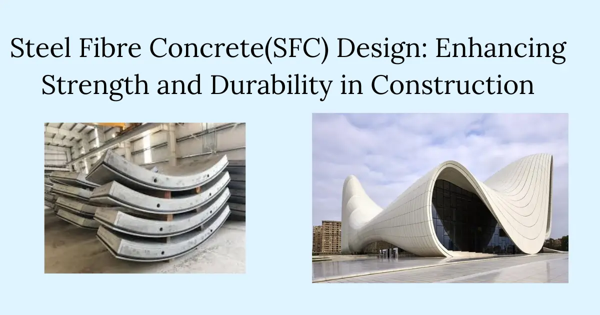
Steel fiber concrete is a revolutionary material that has transformed the construction industry. The use of fibers in concrete has enabled the creation of structures that are more durable, ductile, and far more strong. Steel fiber concrete achieves this added strength and performance by limiting cracks and thereby increasing the ductility of the concrete. This blog post will explore its composition, types, applications, history, and design principles.
What is Steel Fibre Concrete?
Steel fiber concrete is a composite material consisting of hydraulic cement, fine and coarse aggregates, and discrete discontinuous steel fibers. The steel fibers act as crack arrestors, restricting the growth of microcracks and delaying the formation of macro-cracks. This results in improved strength, impact and fatigue resistance, and ductility.
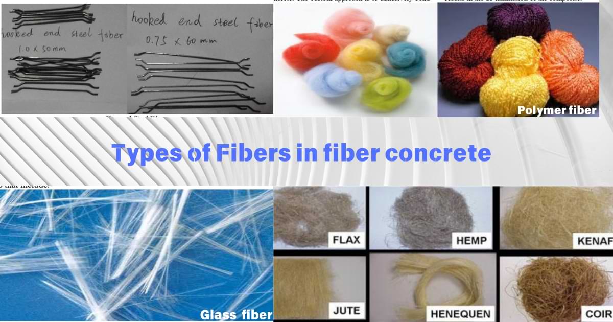
These fibers, typically 4-5 cm long, are added at a ratio of 25-100 kg per cubic meter of concrete, depending on the required reinforcement level. Even if the name suggests steel fibers, the fibers can be made from other materials such as glass, polymers, natural fibers, and synthetic plastics.
Generally, SFC is very ductile and particularly well suited for structures that are required to show high performance of strength and durability such as:
– High fatigue strength resistance to impact, blast, and shock loads
– Resistance to forces due to shrinkage of concrete
-Tensile strength, very high flexural, shear strength resistance
– Erosion and abrasion resistance to splitting
– Temperature fluctuations resistance,
– seismic force resistance
Historical Background of Fiber reinforced concrete
The concept of fiber reinforcement in concrete can be traced back to ancient Mesopotamian times, from 2500 BC. Dwellings in those times were made from natural fibers like straw mixed with clay to create strong construction materials. In the mid-19th century, steel wool was tried as a reinforcement, but the practice ceased due to concerns that it rusted quickly.
However, the modern use of steel fibers in concrete began in the 1960s as engineers sought to improve concrete’s tensile and impact resistance. Advances in producing high-performance steel fibers and improved mixing techniques have since made steel fiber concrete a reliable alternative to traditional reinforced concrete in many applications. The development of hooked-end and deformed steel fibers has further increased the efficiency of SFC, making it a widely used material in modern construction.
What is the difference between fiber concrete and reinforced concrete?
The tendency to call fiber concrete,’ reinforced’ may be confusing because fiber concrete has different properties than reinforced concrete. In reinforced concrete steel is used to mainly resist bending moment. However, fibers have an insignificant contribution to resistance against bending moment. The primary applications of fibers are to resist cracking and improve fatigue-related durability failures. Some researches indicate that there is a high potential for the use of fiber concrete for shear resistance.
Fiber concrete is incorrectly named ”fiber reinforced concrete” since fibers are not reinforcing material as steel bars are considered in the reinforced concrete industry. In various literatures, the name steel fiber reinforced concrete also is not appropriate as there are other types of fibers other than steel. Hence, fiber concrete is called with names as steel fiber concrete or steel fiber reinforced concrete in other literatures although it refers to the same material.
But what is the difference between steel fiber concrete and reinforced concrete? In conventional reinforced concrete, the reinforcement is carefully distributed along the structure member where it is needed. Hence tension reinforcement is provided in high-tensile areas. However, steel fibers are homogenously distributed along the structure members and they can not ensure the same effect of resistance as steel bars do. This makes the loss of resistance after the cracking point inevitable, but in the case of the fiber concrete, the member will have residual resistance that enhances its ductile property. The residual resistance is the result of the fibers taking action and arresting the developed cracks, hence enabling more resistance for the member.
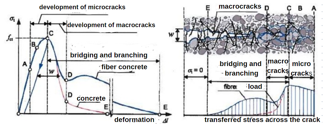
The diagram below illustrates how fiber-reinforced concrete (SFC) behaves differently from plain concrete during loading and cracking. While plain concrete shows brittle failure after reaching its peak strength (shown by the red line’s sharp drop), SFC demonstrates a more ductile behavior (blue line) through three key stages: initial elastic response, microcrack development, and finally macrocrack formation with fiber bridging.
The right-side illustration shows how fibers bridge across cracks, transferring stresses and maintaining structural integrity even after initial cracking. This bridging mechanism allows SFC to continue carrying significant load after cracking occurs, resulting in higher toughness and better crack control compared to plain concrete. The stress transfer diagram at the bottom right shows how the load is gradually distributed across the cracked section through the fiber bridging action, enabling the more gradual and controlled failure mode that makes SFC more reliable in structural applications.
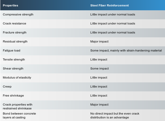
The table below shows the difference of the properties of steel fiber reinforcement as compared to conventional concrete.
Types of Steel Fibres
Steel fibers come in various shapes, sizes, and materials to suit specific construction needs. The primary types include:
- Hooked-End Fibres: These fibers have hooks at both ends to provide better anchorage and bond strength with the concrete. This shape improves the pull-out resistance, ensuring stronger bonding. It is widely used in industrial floors, parking lots, road pavement, etc
- Straight Fibres: As the simplest form of steel fibers, these provide basic tensile reinforcement. While they are easier to manufacture, their bond with concrete is weaker compared to hooked or deformed fibers.
- Crimped Fibres: The crimped shape increases bonding with the concrete, providing improved load transfer. These are effective in controlling crack propagation and offer enhanced pull-out resistance.
- Twisted Fibres: Twisted steel fibers enhance the interfacial bond, allowing for better crack resistance and improved post-crack behavior. The twisting increases the mechanical interlock with the concrete matrix.
- Deformed Fibres: These have deformations along their length to increase frictional resistance, enhancing their bond with the concrete matrix. Deformed fibers offer improved anchorage and are ideal for applications requiring higher pull-out resistance.
- Double duoform: A specialized shape with multiple bends or deformations along the fiber length.
- Ordinary duoform: A fiber with a single bend or deformation, typically less complex than the double duoform.
- Paddled: Fibers with flattened ends, resembling paddles, which enhance anchorage in the concrete matrix.
- Paddled: Fibers with flattened ends, resembling paddles, which enhance anchorage in the concrete matrix.
- Enlarged ends: Fibers featuring bulbous or widened terminations, improving pull-out resistance.
- Enlarged ends: Fibers featuring bulbous or widened terminations, improving pull-out resistance.
- Irregular: Fibers with non-uniform shapes or surface textures, providing varied anchorage points.
- Indented: Fibers with notches or indentations along their length, increasing bonding with the concrete.
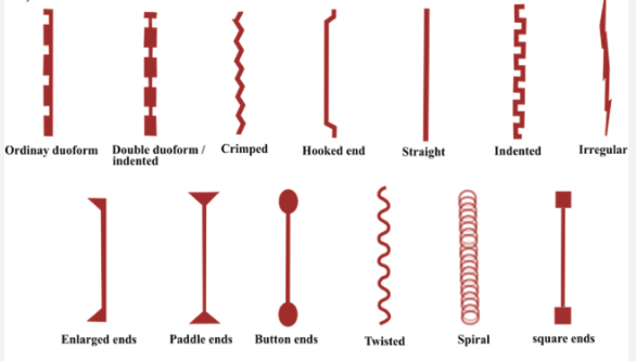
Courtesy of photos https://www.sciencedirect.com
These fiber types are designed to enhance concrete performance by improving tensile strength, crack resistance, and overall durability. The specific shape and design of each fiber type affect its bonding characteristics and mechanical anchorage within the concrete matrix.
These fibers are typically produced through methods such as cold-drawn wire, cut sheet, or melt extraction.
Applications of Steel Fibre Concrete
Steel fiber concrete (SFC) finds applications in numerous construction projects: Fiber is applied as concrete in the form of a cast in situ fiber concrete or as sprayed fiber concrete or shotcrete.
A.Direct Design Applications (where flexural strength is used directly):
The residual flexural tensile strength is directly used in the design.
1. Industrial floors
2. Tunnel linings
3. Bridge decks
4. Concrete pavements
5. Precast elements
6. Shotcrete applications
7. overlays
Concrete Pavements:
- Example: In a highway pavement design, if the flexural strength is 4.5 MPa
- The pavement is designed to withstand repetitive vehicle loads based on this value
- The fiber reinforcement helps distribute loads and prevent cracking
B. Indirect Design Applications (where flexural strength is converted to tensile strength):
Flexural design is applied in Beams, walls, and elevated slabs. The flexural strength is converted to tensile strength.
Example: In a beam design
If the measured flexural strength is 4.0 MPa
This is converted to pure tensile strength (typically around 50-60% of flexural strength)
So the tensile strength used in design might be approximately 2.0-2.4 MPa
The relationship between flexural and tensile strength is important because:
Flexural strength is easier to measure in laboratory tests. It provides a more reliable indication of the material’s performance under real-world conditions. The conversion to tensile strength allows engineers to use standard design equations and codes
Uses of Steel Fibre in Construction Projects
UHPC Structures:
Ultra-High Performance Concrete structures benefit from the added strength and durability of steel fibers.
Industrial Flooring
Industrial Floors and Pavements: To resist heavy loads and dynamic forces caused by forklifts, trucks, and other heavy equipment. SFC minimizes joint spalling and curling, leading to longer service life. Used in Slab-on-Ground for floors to minimize shrinkage cracks and control settlement.
This application is commonly seen in
– Warehouse floors
– Manufacturing facilities
– Loading docks
– Benefits: Reduced crack width, higher load capacity, reduced maintenance
Transportation Infrastructure
Bridges and Roadways: Enhances the durability and impact resistance of road surfaces, reducing maintenance costs and increasing the lifespan of roads and bridge decks.
Airport Runways and Taxiways: To withstand heavy loads from aircraft wheels and prevent cracking caused by thermal and mechanical stresses.
Underground Construction
Tunnel Linings: Used in shotcrete to improve crack resistance and support, especially in underground tunnels where continuous structural integrity is critical.Shotcrete Applications: Applied through spray application in tunnel linings and slope stabilization works. It provides a continuous support layer with better adhesion and crack control.
– Tunnel linings
– Mining applications
– Shotcrete applications
– Benefits: Improved impact resistance, reduced rebound in shotcrete
Precast Elements
Precast Concrete Products: Used in precast pipes, manhole covers, and panels to improve their load-bearing capacity and resistance to impact forces. Provides additional strength and reduces the need for conventional rebar. It simplifies production and accelerates construction schedules.
– Architectural panels
– Pipes
– Barrier walls
– Benefits: Reduced conventional reinforcement, improved handling strength
Structural reinforcement in Hydraulic Structures, Seismic resistant structures, and elevated building structures:
Used in dams, spillways, and canals to resist high water pressures and to provide impact resistance from debris and floating objects.
Seismic-Resistant Structures: The ductility and energy absorption capacity of SFC makes it ideal for earthquake-prone areas, where it helps dissipate seismic energy.
Structural Reinforcement: Used in load-bearing elements like beams, columns, and walls to enhance tensile and shear strength. It replaces or supplements traditional rebar, reducing congestion and improving constructability.
How to determine the characteristic strength of SFC
The primary function is to reduce cracks, which in turn will improve the deformability characteristics or ductility. In some cases, the fibers can also contribute to increasing the bending strength, thus enhancing ductility.
Ductility parameters are an important measure of the performance of steel fiber concrete which are measured during characterisation lab tests of fiber concrete specimens. Design strength is determined using parameters called residual stress factors since ductility parameters are not sufficient for designing members.
The ductility property is significant in pure tension and bending tension. Bending is the usual loading case and the bending test is the most convenient to perform, hence the four-point loaded bending test is used in ASTM C1018 to measure the effect of fibers in concrete. A parameter ductility index is calculated to use in the characterization of the fiber concrete specimens. In the case of the European standard, a notched fiber beam is tested according to EN 14651.
In the case of sprayed fiber concrete (shotcrete slab) tests, square slab tests and round determinate slab tests are performed to get more accurate results than beam test which gives a high scatter of results.
Hence, In characterizing the residual strength of normal fiber-reinforced concrete and fiber spray concrete, different testing methods are utilized to reflect their distinct applications and performance under stress. For normal fiber concrete, residual strength is typically assessed using standardized flexural tests (e.g., ASTM C1609 or EN 14651), where a notched beam is subjected to controlled loading to measure the post-crack load-bearing capacity. In fiber spray concrete, residual strength evaluation is adapted to sprayed application techniques, commonly using panel tests like the round panel test (ASTM C1550)
Mechanical properties of Steel Fibre Concrete
The design of steel fiber reinforced concrete follows similar principles to traditional reinforced concrete design. The design of fiber concrete is more or less based on tests and experience since it is difficult to analyze the action of a single fiber in concrete. The design of fiber-reinforced concrete is guided by standards such as AC I 544 .4R-1 8 and Key considerations include:
1. Compressive strength (up to C50/60 concrete grades). Fibers do not significantly increase the concrete strength hence the concrete strength of the concrete mix without fiber is taken as the compressive strength. The same modulus of elasticity and poissons ratio is taken except after cracking the beam deflection is large so the modulus of elasticity can not be that from the compressive test.
2. Tensile strength
Steel fibers do not increase the tensile strength of concrete, but improve the post-cracking behaviour making it more resistant to cracking and increasing its ductility. Adding steel fibers improves crack control, flexural strength, and overall durability of the concrete. The ratio of fiber length to diameter affects the concrete’s tensile properties
3. Flexural strength
Flexural tensile strength also called flexural strength the main strength for fiber concere. For Concrete pavements, Industrial concrete floors, concrete overlays, and shotcrete for rock strengthening, it is directly used in the design. For other applications beams, walls and elevated slabs flexural strength is the primary strength measured but in the design is used as the basic value that is transferred to other strength values usually (pure) tensile strength.
4. Crack control
Steel fibers become distributed throughout the concrete matrix, resisting the formation and propagation of small cracks. Fibers form a three-dimensional reinforcing matrix within the concrete. Fiber reinforcement helps redistribute accumulated stress from applied loads and shrinkage.
5. Ductility
The concrete’s ductility plays an important role in measuring the residual flexural tensile strength. The ductility property influences the residual strength after initial cracking.
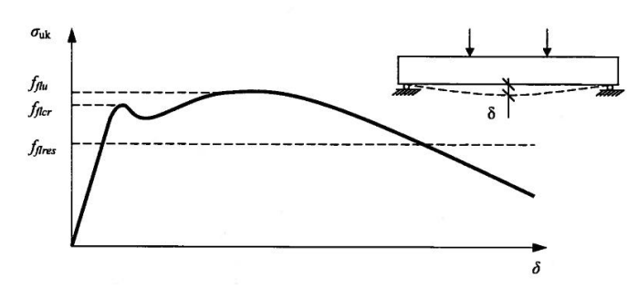
The behavior of fiber concrete under loading is shown in the following diagram. This diagram shows a typical load-deflection curve (σ-δ curve) for fiber-reinforced concrete (SFC) under flexural loading, with a complementary beam sketch showing the loading configuration.
Key Parameters:
1. σ(Vertical axis): Represents the flexural stress
2. δ (Horizontal axis): Represents the deflection/displacement
3. fftu: Maximum/peak flexural strength
4. fficr: First crack strength – where initial cracking begins
5. ffres: Residual strength – the remaining strength after cracking
The curve shows three distinct phases:
1. Initial linear elastic phase up to the first crack
2. Post-crack behavior with some strain hardening
3. Gradual softening phase with maintained residual strength
This type of curve is particularly important because it demonstrates how fiber-reinforced concrete maintains significant strength even after initial cracking, unlike plain concrete which would fail in a brittle manner. The residual strength (ffres) is a key parameter that shows the material’s ability to continue carrying load after cracking, which is one of the main benefits of fiber reinforcement.
Design Principles of Steel Fibre Concrete
Designing SFC involves understanding the contributions of steel fibres to the concrete’s tensile, flexural, and shear properties. Key design principles include:
- Uniform Distribution: Steel fibers must be uniformly distributed to ensure consistent mechanical performance throughout the concrete. Achieving proper dispersion is crucial to avoid weak points.
- Stress-Strain Relationship: The addition of steel fibers changes the stress-strain curve of concrete, improving its post-crack behavior. This allows the material to sustain loads even after cracking.
- Fiber-Matrix Interaction: The bond between steel fibers and the concrete matrix determines the overall strength and ductility of the material. Proper anchorage and frictional resistance are essential for optimal performance.
- Crack Width Control: By bridging cracks, steel fibers limit the width of cracks, thereby enhancing durability. This is essential in hydraulic structures and pavements where water ingress must be minimized.
The design is based on either elastic analysis or plastic analysis depending on the type of the structure, in the first case the design is based on the flexural strength at cracking. For The plastic case such as yield line theory, the design is based on residual strength values. Pavements are rarely designed with yield line theory.
The derivations of residual flexural stress and the relation with tensile strength
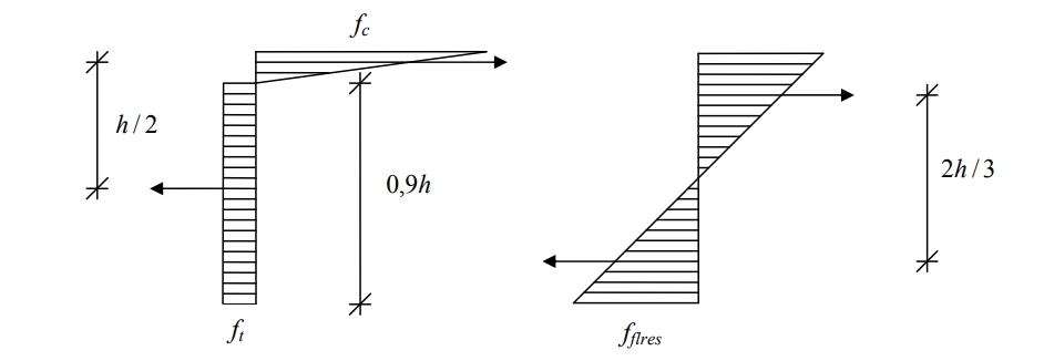
The calculation of residual stress distribution in fiber-reinforced concrete differs from the initial combined compression-tension state. A fictitious linear stress distribution is used to match the actual plastic stress distribution for design purposes. The use of the determination of flexural strength this way is applied to beam tests since they are the simplest and most common method of lab tests of flexural strength.
From the stress distributions shown in the Figure below, two-moment equations can be derived.
For the fictitious linear stress distribution (M1) with triangular residual stress over 2h/3 height, the moment can be calculated as M1 = fflres × b × (2h/3) × (h/3) = (fflres × h² × b)/6, where fflres is the residual flexural strength, h is the section height, and b is the section width.
For the actual stress distribution (M2) with compression fc and tension ft over a rectangle of height 0.9h respectively, the moment is M2 = ft × b × h/2 × 0.9h = 0.45 × ft × h² × b.
The residual strength can then be determined from the measured moment using fflres = 6M1/(h²b). The tensile strength can be determined by equating M1=M2.
If \( M_1 = M_2 \), then:
\[
f_t = 0.37 \cdot f_{\text{flres}}
\]
While direct tension tests provide better stress-crack width relationships needed for some design methods, flexural beam tests are more commonly used due to their simplicity and better representation of practical applications.
1. Direct design of Fiber Steel Concrete
The flexural strength is directly used in the designing of members.
For industrial floors , the yield line theory is normally applied.
The moment is calculated from yield line theory considering possible failures. For example for pile-supported slabs, the Swedish Concrete Society recommends the failure yield line for pile under slab as shown below
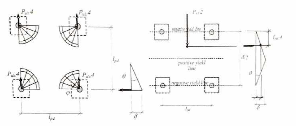
For the interior parts of the slab, the design moment can be obtained from the two failure modes.
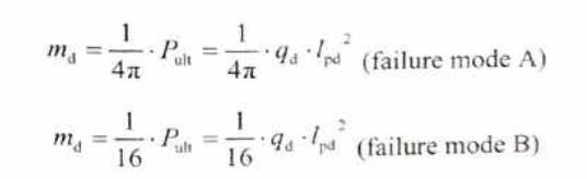
The thickness of the fiber concrete slab can be calculated from the formula
The moment capacity is calculated from the formula
f_{fl} = \text{Design value of the flexural tensile strength of the fiber steel concrete}
2. Indirect design of Fiber Steel Concrete
In the Swedish standard, the moment capacity is calculated by analyzing the combined effect of the concrete’s compressive strength in compression,. The fiber concrete in tension and the conventional reinforcement steel is in tension.
The difference with the direct design is the flexural tensile strength is converted to pure tensile strength for use in the calculations.
There are three distribution of the stress with diminishing levels of complexity.The residual flexural tensile strength provided by steel fibers is incorporated as an additional stress block in the tension zone
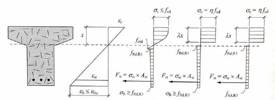
The moment arm is not known. So the section h is divided in to several sections. For ex. Start with x=0.1*h or 0.2*h. The parameters Values of the parameters η\etaη and λ\lambdaλ (defined in Figure) are provided in Eurocode 2
“The design incorporates a control of maximum strain. On the compressive side, εc<εcu3\varepsilon_c < \varepsilon_{cu3}εc<εcu3 according to Eurocode 2. Specifically, εcu3=3.5 \permil\varepsilon_{cu3} = 3.5 \, \permilεcu3=3.5\permil .On the tension side (i.e., tensioned steel fiber concrete), the maximum strain εtu\varepsilon_{tu}εtu is determined by the following equation (Figure 5.4):”
εma=εct+wulcs(5.7)\varepsilon_{ma} = \varepsilon_{ct} + \frac{w_u}{l_{cs}} \quad (5.7)
where:
- εct=fctdEc\varepsilon_{ct} = \frac{f_{ctd}}{E_c}, with fctdf_{ctd} being the design value of the concrete tensile strength and EcE_c the modulus of elasticity of concrete.
- wu=2.5 mmw_u = 2.5 \, \text{mm}, representing the crack width.
- lcsl_{cs} is the characteristic length, typically set to lcs=0.8×hl_{cs} = 0.8 \times h, where hh is the section height.
The benefits of fiber-reinforced concrete
The use of fiber in reinforced concrete offers significant benefits across various aspects of construction, including structural design, cost, quality, and construction performance. Here’s a comprehensive overview of these benefits, including material and cost reduction percentages for different types of buildings and infrastructure:
Structural Design Benefits
1. Enhanced durability and crack resistance
2. Increased impact and fatigue resistance
3. Improved tensile strength and ductility
4. Better control of plastic and drying shrinkage cracking[1][6]
Cost Benefits
1. Overall project cost reduction: Up to 70%[2]
2. Construction time reduction: Up to 48%[2]
3. Reduced maintenance costs due to improved durability[7]
Quality Improvements
1. Enhanced resistance to environmental factors
2. Improved surface quality and aesthetics
3. Better fire resistance (with certain fiber types)[1]
Construction Performance and Productivity
1. Simplified construction process
2. Faster construction times
3. Reduced labor requirements[2][7]
Material Reduction
1. Steel usage: Up to 45% reduction[2]
2. Concrete volume: Reduced slab thickness[9]
Cost and Material Reduction by Building/Infrastructure Type
Light Rail Projects
– Cost reduction: Nearly 70% (from $17.5 million to $5.3 million per mile)
– Construction time reduction: 48% (from 231 to 121 days per mile)
– Steel usage reduction: 58% (from 482,000 to 203,000 pounds per mile)[2]
Industrial Floors
– Joint forming costs reduced due to wider joint spacing
– Reduced slab thickness, saving on concrete and placement costs
– Simplified construction process, eliminating steel fabric positioning errors[9]
Elevated Buildings
– 12-story steel fiber-reinforced concrete (SFRC) building:
– Time savings: 34.1 days (5.44%)
– Cost savings: 4.88% (direct costs) and 1.27% (total project costs)[8]
General Infrastructure
– Reduced maintenance costs due to improved durability and crack resistance
– Longer useful life of structures
– Greater impact resistance and fatigue endurance[9]
Additional Benefits
1. Increased design flexibility
2. Enhanced sustainability due to reduced material usage
3. Improved workplace safety
4. Three-dimensional reinforcement within the concrete matrix[5]
In conclusion, fiber-reinforced concrete offers substantial benefits across various construction applications, providing significant improvements in structural performance, cost-effectiveness, and construction efficiency. The specific percentages of cost and material reduction can vary depending on the project type and scale, but the overall advantages make it an increasingly attractive option for modern construction projects.
Sources:
[1] https://www.becosan.com/steel-fibre-reinforced-concrete/
[2] https://www.cnsteelfiber.com/products/
[3]https://construction.bekaert.com/us/en/blog/evolution-of-industrial-floors-a-history-of-dramix-steel-fibers
[4] https://www.rilem.net/images/publis/1507.pdf
[5] https://dtc.sa/article/steel-fiber-reinforced-concrete-properties-applications-and-design/
[6] https://www.jsce.or.jp/committee/concrete/e/newsletter/newsletter05/8-Vietnam%20Joint%20Seminar(CHANH).pdf
[7] https://www.linkedin.com/pulse/types-steel-fiber-nikhil-nandan
[8] https://www.readymesh.com/further-details/historical-background/
[9] https://www.rilem.net/images/publis/122603.pdf
[10] https://steel-fibre.com/blog/keyadvantagesofsteelfiber