
Geometric design practices for railways and highways share fundamental principles but differ significantly in execution due to operational requirements and vehicle dynamics.
The difference in operational characteristics and vehicle dynamics results in significantly different geometric constraints. Railways require gentler curves and more restrictive gradients due to the physics of steel wheels on steel rail systems and trains’ limited climbing capability.
While both transportation modes balance cost-effectiveness with safety and operational efficiency, railways follow more stringent design parameters that limit their flexibility in navigating challenging terrain. In contrast, highways can more easily conform to existing landscapes.
Fundamental Concepts of Alignment Design
Alignment in transportation engineering refers to the three-dimensional geometric design defining a route’s path through the landscape. It consists of horizontal alignment (the route in plan view) and vertical alignment (the elevation profile). For both railways and highways, proper alignment design serves several critical functions:
Transportation alignment must satisfy minimum geometrical requirements, minimize conflicts with existing infrastructure, serve appropriate destinations, and keep engineering costs manageable. Finding the most cost-effective path through topography and following existing transport corridors is generally a common starting point for both railways and highways.
Design Integration
For both railway and highway design, horizontal and vertical alignments cannot be considered separately, especially in hills, valleys, and mountainous areas.
There is a maximum height above terrain beyond which alignments become uneconomic due to capital costs in building high structures.
Therefore, horizontal alignments might need to take very different paths to satisfy vertical alignment limits and vice versa.
Key Differences in Geometric Design Parameters
Horizontal Alignment Constraints
Railways
- Prioritize straight paths or gentle curves for high-speed stability
- Use transition curves for speed >40 km/h to avoid abrupt directional changes
- Minimum radius determined by design speed and superelevation
- Single-track layouts dominate, requiring narrow right-of-way
Highways
- Follow natural terrain contours with adaptive curvature
- Allow sharper curves due to lower design speeds and vehicle maneuverability
- Multi-lane configurations require wider rights-of-way
- Minimum radius determined by design speed, superelevatio,n and side friction

Horizontal Curve Radii Requirements
One of the most significant differences between railway and highway alignment is the minimum radius of horizontal curves:
For railways:
- Minimum radius for high-speed railway typically ranges from 6,000m to 8,500m, depending on maximum design speed
- The nominal minimum radius is recommended to be 4,000m for standard mixed-traffic railways
- For freight-only railways, the recommended minimum radius is 900m
- Absolute minimum radius (not on main tracks) is 300m, with exceptional cases at 150m
Minimum radius of curve Rₘᵢₙ Formula for railway cant :
Rₘᵢₙ(m) ≈ 11.8 × (V km/h)² ÷ E in mm
Imperial Version:
Rₘᵢₙ(ft) ≈ 4.0 × (V in mph)² ÷ E in inches
Adjust for Unbalanced speed:
Rₘᵢₙ(m) ≈ 11.8 × V² ÷ (E + Cant Deficiency)
For highways:
In contrast, highways have much less restrictive requirements. For Highway horizontal alignment, the minimum radius depends on the design speed and can vary between 80 ft-1000 ft(20m-300m)
The ruling minimum radius is calculated based on design speed, superelevation, and friction to counteract centrifugal forces, as given by AASHTO.
R_min = V^2 / [127 * (e_max + f_max)] ,feet
for emax(4-8%), fmax(0.14-0.32).
For aesthetics:
Minimum curve length is often set at 15V (feet) for rural highways.
While no strict maximum exists, practical limits may arise from avoiding extensive land acquisition, driver perception from long, gradual curves, and drainage problems.
This fundamental difference means railways require more land acquisition and have less flexibility navigating around obstacles compared to highways.
Minimum Length of straight lines and horizontal curves
In railway alignments, minimum lengths for horizontal curves and straight lines are specified to ensure safety, passenger comfort, and efficient train operation.
Longer curves reduce lateral forces, minimize derailment risk, and decrease wear on wheels and rails. Adequate straight lengths provide space for smooth transitions, clear visibility, and stable placement of stations, signals, and turnouts.
In railway alignment, the minimum length of horizontal curves is: for Mixed traffic lines, L(m)>=Vmax/1.2, Vmax in km/ h, and for Passenger traffic lines, L>=L/2; V=240 km/h
On the other hand, for main highways and primary roadways, the minimum length of horizontal curves (Lc min) should be 15 times the design speed expressed in mph, or mathematically expressed as: Lc min = 15V (where V is design speed in mph)
There is also a minimum length for ensuring sight distances towards obstructions. However, there is no limit to straight tangent lines.
Transition Curves
Both transportation modes use transition curves, but railway design has stricter requirements:
Railway design discourages overlapping of vertical curves with horizontal transition curves or turnouts3
Transition Curves used are clothoids or parabolas in railways, and are Mandatory above 40 km/h in railways. The length of transition curves is selected to ensure a constant rate of change of cant with 3 ways. The first is the calculation to check the length with allowable cant gradient (dD/ds – cant gradient = 2,5 mm/m). The second is to check the change of cant as per time(dD/dt – rate of change of cant (30 mm/s) ). The third is for mixed traffic of passenger and freight trains to check cant deficiency gradient(dI/dt – rate of change of cant deficiency (30 mm/s).
In highways, transition curves are also clothoid, parabolas, or other types of curves. They are optional for low-speed roads. In highways, the superelevation is rotated gradually to ensure a smooth centrifugal force change that ensures users’ adequate driving comfort.
Vertical Alignment Constraints
Gradient Limitations
Railways have significantly more restrictive gradient limitations:
- For mainline railways (open line): nominal gradient limit is 8‰ (0.8%), maximum limit is 12.5‰ (1.25%)
- In station areas: nominal gradient is 0‰, maximum limit is 1.5‰, exceptional limit is 2.5‰
- Heavy haul freight lines have even more restrictive gradient requirements

Highway designs can accommodate much steeper gradients, typically ranging from 4% to 8%, depending on terrain and road classification, allowing highways to follow natural terrain more closely and reduce earthwork costs.

Vertical Curves
While parabolic curves are common in road design and sometimes in rail, EN 13803 specifically allows or prefers circular curves. Railways have specific requirements for vertical curves:
- Maximum vertical curve radius is limited to 40,000m
- Minimum vertical curve radius is 10000 m for main tracks and 2000 m for stations
- The number of vertical elements is recommended to be limited to 4 per sliding kilometer
- Recommended minimum distance between the sag and the crest of the vertical profile is 600m
Highway vertical curves are typically designed as parabolic curves rather than the circular ones used in railways, and can be shorter with smaller radii.
The minimum vertical curve length of a highway is the minimum of
1) sight distance(SSD) requirement given by L=K*A. Where, K: Rate of vertical curvature (varies by design speed), A: Algebraic difference in grades (%)
2)Aesthetic Minimum length = 3×design speed (mph); 3)Absolute minimum of 90 ft (27 m) for practical construction
Maximum Vertical Curve Length limited by K=167 for drainage considerations.
Minimum Length of vertical radius and constant gradient
In railway alignment
Minimum vertical radius prevents jerky, uncomfortable, and unsafe transitions in elevation.
Constant gradient ensures smooth, efficient, and safe operation of trains, particularly on long stretches.
For mixed traffic: Nominal value Lv(m)>=Vmax/2, Vmax(km/h),
For passenger traffic Lv>=V/2, V=249 km/h
In highways, minimum vertical curve lengths are calculated to ensure adequate sight distances. In highways Minimum vertical curve length is often calculated as 3 × design speed (mph) in the US, or that which fulfils the sight distance requirement
There is a maximum length of gradients uphill because it affects the vehicle’s speed.
Track Cant and Superelevation
Highways can have superelevation ranging between 4-10%, depending on the type of terrain and traffic type.
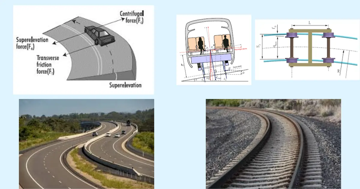
While both railways and highways use superelevation (called “cant” in railway engineering) to negotiate curves, the application differs:
In railways, the track cant is the only parameter considered to counteract centrifugal forces. However, in highways, friction force and superelevation are both considered in the superelevation calculations.

In highways, superelevation helps balance vehicles on curves and is given by:
e + f = v² / (g × R)
where:
– e = road superelevation (as a fraction, e.g., 0.07 for 7%)
– f = lateral friction factor
– v = speed (in m/s)
– g = acceleration due to gravity (9.81 m/s²)
– R = radius of the curve (in meters)
In railways, cant (superelevation) is used for the same purpose and is given by:
E = 11.8 × V² / R
where:
– E = railway cant (in mm)
– V = train speed (in km/h)
– R = radius of the curve (in meters)
There are also terms called cant deficiency and excess that apply only in railways in mixed traffic, that is, when trains of different speeds run on the lines. Cant deficiency occurs when the provided cant is lower than the theoretical value, and excess is when the provided cant is higher than the theoretical value.
If trains go faster than the balanced speed, cant deficiency (I) is allowed, so the total equation becomes:
E + I = 11.8 × V² / R
Highways rely more on friction, while railways use cant to reduce wear and improve comfort.
For high-speed rail using European (TSI) standards, radius limits can be relaxed if slab track is used because higher Cant Deficiency is permitted on slab track compared to ballasted track. However, this requires early decisions on track type in the alignment design process.
Curvatures in railways enforce speed restrictions through superelevation and cant deficiency limits.
- Cant limits (vertical outer rail elevation):
- Normal: ≤150 mm (UK), ≤6 inches (152 mm U.S.)
- Exceptional: ≤180 mm (UK), up to 11 inches (280 mm) in Europe with tilt trains
- Cant deficiency limits (uncompensated lateral force):
- Normal: ≤110 mm (UK), ≤3 inches (76 mm U.S.)
- Exceptional: ≤300 mm (UK), ≤6 inches (152 mm U.S. by waiver)
At station platforms, cant is limited to 70mm, especially where trains may or may not stop at platforms.
Highways do not have cant deficiency like railways, as the concept is specific to railway engineering due to the unique dynamics of trains on curved tracks.
What is Cant Deficiency in Railways?
Cant deficiency occurs when the actual superelevation (cant) provided on a railway curve is less than the equilibrium cant required for a train traveling at a specific speed. This results in lateral forces acting more on the outer rail, which can affect passenger comfort and track wear. It is used to balance operational speeds for mixed traffic (e.g., freight and passenger trains) and reduce excessive cant that might hinder slower trains.
Why Highways Don’t Have Cant Deficiency
- Superelevation in Highways: Highways also use superelevation (banking of curves), but vehicles on highways are much more flexible in terms of speed and lateral force handling compared to trains. Rubber tires provide better friction and grip, allowing vehicles to navigate curves without needing precise equilibrium cant as in railways.
- Dynamic Control: Unlike trains, road vehicles can individually adjust their speed based on the curve’s geometry, eliminating the need for a fixed “deficiency” concept.
- Operational Differences: Trains are constrained by fixed tracks, while road vehicles operate independently, making cant deficiency irrelevant for highway design.
While both railways and highways use superelevation to aid in cornering on curves, cant deficiency is unique to railways due to their fixed path and operational constraints.
Sight distances
Highway design needs calculation of sight distances to ensure that a sufficient length of road with a clear view of the obstruction is available ahead. The Calculations involve the estimation of braking distance that utilizes the friction for braking.

However, railways are not dependent on friction for stopping before obstructions ahead, as railway braking curves are long, taking 2-3 km to stop.

Hence, in place of braking, railway lines use signals and switches to control the movement of trains.
In highways, drivers have more control and flexibility of movement, which is possible because of the use of steering wheels and brakes. Trains are controlled by signalers, central train controllers, and signal systems.

The train driver only watches the engines and other systems functioning, follows instructions from signals, and follows routing schedules from the central control center. Hence, train drivers are there to monitor the well functioning of the systems and act in case of malfunctioning or changes to schedules.
Signals, Switches, and Crossings Placement
Railways and highways both use signal systems. The signal system in highways is used to control the traffic so that there are no accidents and there is smooth and well-functioning highway traffic.
In railways, the signal system is also used to prevent accidents, like on highways. However, the signal system in railways also partly replaces the work of the steering wheel in cars.
Switches in railways also take the role of steering wheels in cars, directing railway traffic to pre-assigned directions and routes.
Like intersections in highways, crossings also provide junctions where trains will pass over another track or line. So they provide equivalent functions.
Railways have special alignment constraints related to track configuration:
Switches and Crossings (S&C) should be located on straight sections of track. Junctions, passing loops, station throats, perturbation crossovers, and depot access connections need straight sections of alignment with sufficient length to position the S&C away from horizontal transition curves, vertical curves, and adjacent S&C units1.
Cross-Section Design
Railways
- Track bed with ballast, sleepers, and rails.
- Minimal drainage features compared to highways.

Source: Wikimedia
Highways
- Multi-lane layouts with shoulders, medians, and curbs.
- Complex drainage systems for surface water.

Vehicle Dynamics
The inherent differences in vehicle dynamics significantly impact alignment design:
Heavy haul freight lines have different technical parameters from high-speed passenger lines, creating a balance to be struck if lines are built for mixed traffic. The limited ability of trains to climb grades due to steel-on-steel wheel adhesion constrains vertical alignment options.
.
Similarities in Alignment Design Approaches
Corridor Sharing and Route Selection
Both railway and highway alignments often follow similar corridors, or it can be said that it is common for railways to follow existing transport corridors. But when smaller or feeder roads connect to the highway at the intersections, the new railway also has to find a way to cross or go around those spots. This can make designing the railway more complicated, but it also gives a chance to plan for integrated transportation planning.
Both railway and highway designs consider similar environmental, geotechnical, and hydrological factors in route selection, intending to minimize impact while providing efficient transportation services.
Utilities and Infrastructure Coordination
Both railway and highway alignments must coordinate with existing utilities:
New alignments frequently cross or come close to overhead power lines, and site visits are often necessary to confirm transmission corridors and assess wire heights. Sometimes, positioning the alignment near pylon structures (while maintaining sufficient clearances) is beneficial to maximize overhead clearances.
Where oil pipelines are potential crossing points, it’s often not possible to divert them without considerable expense. Rail elevations ideally pass over these, and structures are needed to maintain separation from any part of the railway that might cause vibration.
Hydrological Considerations
Both transportation modes must address water flow and drainage issues:
Building railways or highways across streams and rivers requires consideration of worst-case water flows, flooding, and tidal waters. At low points in the terrain, piped culverts or box culverts are necessary where the alignment crosses watercourses.
In flat areas away from crossing points, railways typically maintain a standard rail level at 1.0 to 1.2m above ground level to ensure that the formation under the track bed can be drained naturally to the surrounding terrain.
Special Considerations for Railway Alignment
Station Area Design
Railways have unique alignment requirements for stations that don’t apply to highways:
Passenger stations should be placed on straight sections, and passenger platforms on curves should be avoided. If curves cannot be avoided at passenger platforms, a minimum radius of 1000m must be respected.
These station requirements create additional constraints for railway alignment that don’t exist for highway design, particularly in urban areas where space is limited.
Sources:
- https://www.thepwi.org/wp-content/uploads/2022/04/Journal-2022_04-Vol140-Pt2_Rail-alignments-for-new-railways.pdf
- https://static.tti.tamu.edu/tti.tamu.edu/documents/164-1.pdf
- https://www.railbaltica.org/wp-content/uploads/2021/06/RBDG-MAN-013-0105_RailwayAlignment.pdf
- http://www.diva-portal.org/smash/get/diva2:675179/FULLTEXT01.pdf
- https://www.studocu.com/row/document/mekelle-university/advanced-software-engineering/compare-the-geometric-design-practices-for-railways-and-highways/80251708
- https://www.irjet.net/archives/V4/i4/IRJET-V4I4270.pdf