
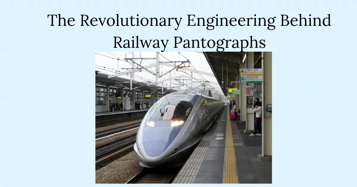
The railway pantograph, a crucial component of electric train systems, has been powering locomotives for over a century. This ingenious device collects electricity from overhead wires and transfers it to the train’s propulsion and auxiliary systems.
History of the Pantograph
The pantograph’s journey began in the late 19th century. In 1889, Walter Reichel of Siemens & Halske in Germany invented the bow collector, an early version of the pantograph.
However, the diamond-shaped pantograph we’re familiar with today was patented by John Q. Brown of the Key System in 1903.

Modern pantograph design, especially half pantographs was a significant improvement over the simple trolley pole and bow collectors, allowing trains to travel at much higher speeds without losing contact with the overhead lines.
The half pantograph, also known as the Z-shaped pantograph, is a type of current collector used primarily on electric trains and trams. This design was developed by Louis Faiveley in 1955 to meet the demands of high-speed rail travel while maintaining a compact and responsive structure.
Components of a modern half Pantograph
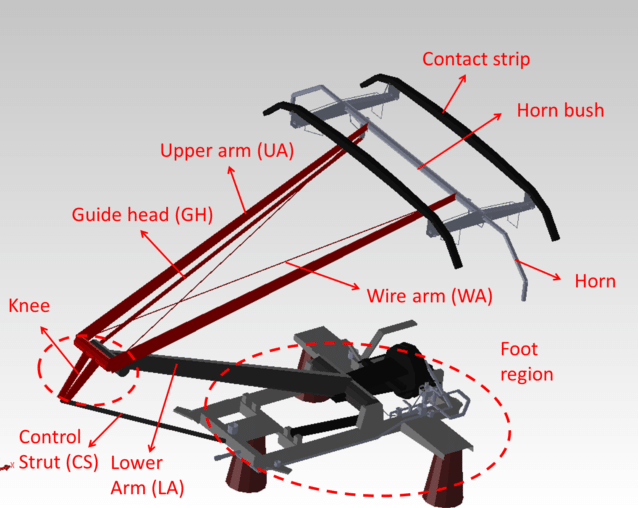
A typical pantograph consists of several key components
1. Frame Assembly: The base structure mounted on the train’s roof
– Horn: The curved structure at the top that helps guide the pantograph along the overhead wire
– Horn bush: Connection point where the horn attaches to the frame
– Contact strip: The topmost part that makes direct electrical contact with the overhead catenary wire
2. Arm Assembly: Includes upper and lower arms that allow vertical motion.
– Upper arm (UA): The upper linkage that connects to the guide head
– Wire arm (WA): Works in conjunction with the upper arm for movement
– Lower arm (LA): The bottom linkage that connects to the base
– Guide head (GH): The component that guides the motion of the upper assembly
– Control strut (CS): Helps control and stabilize the pantograph’s movement
– Knee: The joint where multiple arms connect, allowing for articulation
3. Collector Head: Contains the carbon strips that make contact with the overhead wire.
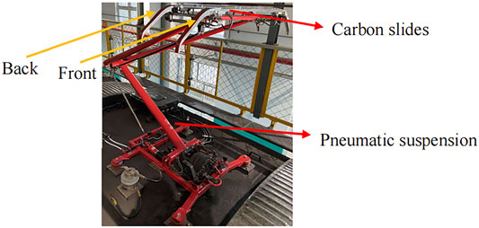
4. Spring and Pneumatic Balancing System: Ensures constant contact force against the overhead line.
Pneumatic balancing systems and springs in pantographs play a crucial role in maintaining consistent contact between the pantograph and the catenary line, ensuring efficient energy transfer for electric trains. Those systems absorb the variations due to different speed and track conditions and the resulting oscillations in the pantograph The springs apply constant force to maintain the contact shoe pressed against the overhead wire.
The pneumatic balancing system utilizes air pressure to adjust the force applied by the pantograph’s contact strip against the overhead wire, adapting to various operational conditions. In some advanced pantograph designs, a pneumatic tension system complements the spring mechanism
The dynamic response from the spring and the pneumatic pressure control is particularly important at high speeds, where aerodynamic forces can significantly affect contact quality at the pantographs collector.
The pneumatic components are strategically located within the pantograph body:
- Transmission Reservoir: Typically situated within the main frame of the pantograph, it connects directly to the springs that control the bow(upper part of the pantograph assembly that holds the contact shoe(s)) or the movement.
- Electro Pneumatic Valves: These are usually mounted near the base of the pantograph or along its arms for easy access and efficient control of airflow.
- Pressure Regulators: Often integrated into the system close to where air enters the pantograph assembly, allowing for immediate regulation of incoming air pressure.
5. Damper Assembly:
It is an oil filled cylinder that is situated between the base frame and lower frame and it compensates the vibrations of the pantograph,
All these components work together to maintain consistent contact with the overhead wire while accommodating changes in height and lateral movement of the train.
Pantograph Overhead Wire Specifications
Contact Wire: The primary wire used for current collection is often made from copper or copper alloys, with standard cross-sectional areas ranging from 80 mm² to 150 mm². The choice of material affects both conductivity and tensile strength, with variations including copper-silver and copper-cadmium alloys.
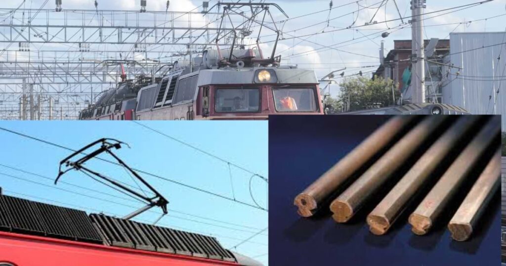
Catenary Wire: This supporting wire typically has a cross-section of 120 mm² or more, depending on the system’s requirements. It is designed to maintain the geometry of the contact wire under various operational conditions
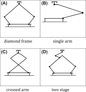
Types of Pantographs
There are two main types of pantographs:
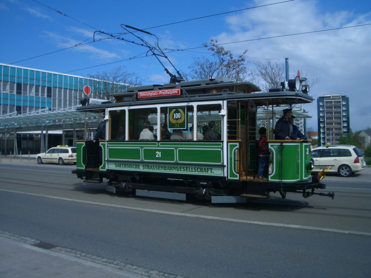
1. Double-arm pantograph: The traditional diamond-shaped design.
2. Single-arm pantograph: A more modern, streamlined design introduced by Louis Faiveley in the 1950s.
How do pantographs work
Modern half pantographs operate by pushing a contact shoe against the overhead contact wire, drawing the necessary electrical power for the train. The mechanism is typically spring-loaded and may be controlled by compressed air, which lifts the pantograph to maintain contact with the wire while allowing for flexibility during travel
Design of Pantograph Wire
The pantograph wire, or contact wire, is designed with several considerations:
1. Zigzag pattern: The wire is installed in a gentle zigzag pattern to ensure even wear on the pantograph.
2. Stagger: On straight tracks or those with large radii, the wire is positioned in a zigzag form called stagger.
3. Curve compensation: For tracks with small radii, the wire is positioned on the outer side of the curve to maintain sufficient contact.
4. Tension: The wire is kept under constant tension to maintain proper contact with the pantograph.
The pantograph system continues to evolve, with engineers still working to optimize its design for higher speeds and better performance. As railway technology advances, the humble pantograph remains a critical link between power source and train, driving us into the future of rail transportation.
Sources:
[1] https://www.wabteccorp.com/trains-of-thought/still-electrifying-after-all-these-years-a-pantograph-appreciation
[2] https://www.youtube.com/watch?v=q87osK9V6H4
[3] https://www.prysmian.com/sites/default/files/business_markets/markets/downloads/datasheets/Pantograph-cables.pdf
[4] https://civengtech.com/railway-overhead-electrification-system-design/
[5] https://en.wikipedia.org/wiki/Pantograph_(transport)
[6] https://www.mersen.com/sites/default/files/files_imported/ptt-current-collection-technical-guide-mersen-en-1601.pdf
[7] https://support.taittowers.com/hc/en-us/articles/1260803066830-Pantograph-Spec-Sheet
[8] https://www.researchgate.net/figure/Pantograph-and-catenary-system_fig1_282217813
[9] https://ethw.org/Electric_Pantographs
[10] https://www.savree.com/en/encyclopedia/pantograph-disconnector