
Retaining walls are among the most challenging structures in civil engineering. They must simultaneously resist enormous lateral earth pressures, manage groundwater, adapt to variable site conditions, and maintain long-term stability—often for decades. Yet many construction failures occur not from lack of ambition, but from overlooking fundamental principles. This comprehensive guide addresses every critical factor that determines whether a retaining wall will perform reliably or fail prematurely.
Understanding the Fundamental Design Requirements
The construction of a successful retaining wall must start with a design that establishes the clear objectives. A retaining wall must satisfy multiple stability requirements simultaneously, each with prescribed minimum safety factors.
The safety factors used in design include sliding resistance (minimum 1.5), overturning (minimum 2.0), bearing capacity (minimum 2.0), and internal stability for reinforced systems (minimum 1.3 to 1.5, depending on the specific failure mechanism).
The selection between wall types is another important step that depends on the desired objectives and site conditions. Gravity walls rely primarily on their own weight to resist soil pressure and are suitable for heights under approximately 4 feet in favorable conditions.
Cantilever walls use a stem and base slab, extending to moderate heights of 4 to 6 feet with proper design. Mechanically Stabilized Earth (MSE) walls employ horizontal geogrid reinforcement through the backfill and can achieve heights exceeding 6 feet, even reaching critical-height specifications for important applications. Each type demands different construction protocols and precision levels.
Conducting Thorough Geotechnical Investigation
Every successful retaining wall project begins with a comprehensive geotechnical assessment. The project may require conducting a geotechnical test report. The report must characterize on-site soils through a hierarchy of investigation methods, beginning with boreholes and test pits to identify soil stratification, and continuing with laboratory analysis of soil samples.
Critical soil parameters in the design include friction angle (preferably tested), unit weights, moisture content, plasticity indices (PI), and liquid limits (LL). These properties determine bearing capacity, shear strength, and water retention characteristics. Standard Penetration Testing (SPT) and plate load testing provide field validation of soil strength, while laboratory testing confirms compressibility and permeability.
For foundation soil and reinforced backfill zones, cohesionless, free-draining materials are preferred—these have less than 10% fines, PI less than 6, and LL less than 30. Soils with low plastic fines (such as SC soils with PI less than 20 and LL less than 40) may be acceptable for lower walls, but require enhanced drainage design.
High-plasticity soils (MH, CH, OH classifications) and organic soils should be rejected entirely, as they cause excessive settlements and unpredictable lateral forces. Groundwater conditions also demand careful evaluation, as rising water tables can increase pressures beyond design assumptions.
Managing Groundwater: The Most Critical Construction Factor
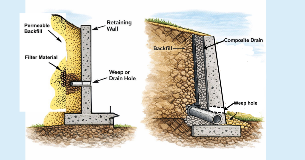
Inadequate drainage is the single most common cause of retaining wall failure. Water infiltrating behind a wall increases lateral pressure, reduces soil shear strength, and can create hydrostatic forces that exceed design capacity. Understanding this threat, all retaining wall designs must incorporate comprehensive drainage systems that address both subsurface water and surface runoff.
The foundation drainage strategy includes a toe drain—a 100mm (4-inch) perforated drain pipe installed at the lowest possible elevation within the first 300mm of wall rock. For MSE reinforced retaining walls , an additional heel drain positions another 100mm pipe at the back bottom of the reinforced soil mass. Both pipes must slope gently downward and exit the system at grades or drainage basins away from the structure.
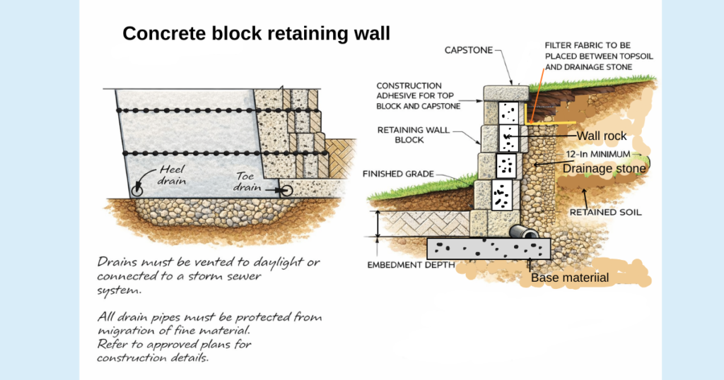
Behind the wall face itself, proper drainage requires layering. The first course of blocks receives a gravel blanket, typically 4 to 6 inches deep, which allows water to drain downward toward the toe drain. This blanket is often topped with geotextile fabric to prevent sediment migration.
Weep holes provide an alternative or supplementary drainage mechanism. These holes, spaced typically 6 to 10 feet along the base course, allow trapped water behind the wall to weep outward, reducing hydrostatic pressure. Ensuring weep holes remain unobstructed requires ongoing maintenance.
Critically, the design must also control external water sources. Surface drainage must be diverted away from the wall; roof downspouts must be sized and routed to carry water clear of the structure; and the site layout must slope away from the wall to prevent surface water from accumulating at the toe. Neglecting these external sources overwhelms even well-designed internal drainage systems.
Base Preparation and Foundation Design
The foundation supports all subsequent loads and is often the governing design element. Proper base preparation determines whether a wall will settle unevenly, tilt, or maintain alignment for decades.
Foundation trenches must extend deeper than the first course of blocks—typically 6 inches deeper than the block height plus an additional 6 inches for the gravel base. In sloped terrain, stepped trenches maintain level block courses while conforming to the natural grade. The excavated surface must be compacted before additional materials are placed
The gravel base layer, typically 4 to 6 inches of crushed stone, serves dual purposes: it provides drainage and prevents uneven settlement. This material must be spread evenly, then compacted thoroughly using a hand tamper or mechanical plate compactor. The compacted surface must be verified as perfectly level in all directions, since any unevenness at this stage compounds upward through the completed wall.
For concrete or timber walls with formal foundations, the construction steps include setting formwork, placing reinforcement if required, and pouring concrete to the necessary thickness (often 20cm for reinforced walls in significant applications). The concrete must cure for the time specified by the mix design—typically 2 to 3 days—during which rain must be avoided.
Critical Soil Compaction Standards
Proper compaction of backfill soil is as essential as proper foundation preparation. This is where many construction projects falter, as compaction appears simple but demands proper execution.
The industry standard for foundation and backfill soils is 95% of Standard Proctor (or 95% of the soil’s maximum dry density).This is prepared as standard through lab tests from the samples from the site. Achieving this requires two parallel efforts: controlling moisture content (soil that is too dry or too wet will not reach the target density) and placing soil in specified lifts.
Soil must be placed in lifts—horizontal layers—not exceeding 8 inches (200mm) in thickness. Each lift is then compacted using appropriately sized equipment. At minimum, two passes with a walk-behind plate compactor are required, and heavy equipment must remain at least 3 feet away from the block face to avoid placing lateral loads on the wall.
On-site testing should be specified in bid documents and performed regularly during construction. Field density tests verify that 95% Standard Proctor has been achieved, and these tests provide documentation of compliance with design specifications. Without such verification, there is no assurance that the wall will perform as designed.
Selecting Materials: Concrete, Timber, and Stone
The choice of wall facing material influences durability, maintenance requirements, aesthetics, and cost. Each material category presents distinct advantages and limitations that merit careful evaluation based on site conditions and project requirements.
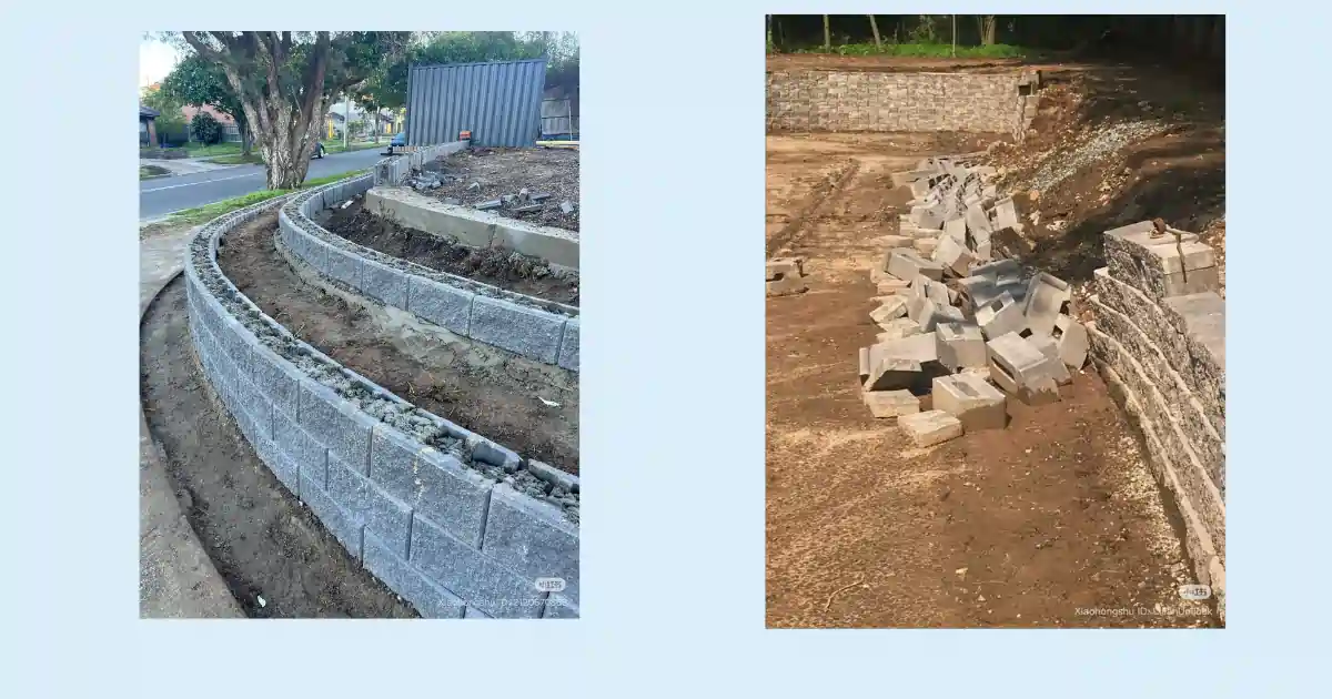
Concrete Block Retaining Walls have become the predominant choice in engineered construction. Concrete blocks offer exceptional durability—typically 30+ years—low maintenance, and excellent resistance to harsh weather including freeze-thaw cycling. Modern interlocking block systems allow aesthetic flexibility; concrete can be finished to resemble natural stone. The modular nature of block systems also accommodates reinforcement design elegantly, with geogrid layers integrated between courses. Disadvantages include higher initial cost and the need for experienced installation to prevent misalignment.
Stone Retaining Walls, employing granite or limestone, combine natural aesthetics with exceptional strength and enhance landscape appeal. Stone performs exceptionally well in erosion control applications and adds prestige to high-end properties. However, stone walls demand skilled installation due to material and labor costs, and the initial investment is substantial.
Timber Retaining Walls represent the most economical option and install quickly, making them attractive to budget-conscious property owners. However, timber has significant limitations: typical lifespan is only 15 years, requiring replacement within a residential property’s ownership cycle. Timber deteriorates rapidly when exposed to moisture, and termite damage is common in susceptible regions. Proper sealing and drainage integration are essential for any extended service life.

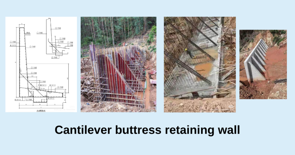
Cast in-situ concrete gravity and cantilever retaining walls are preferred for medium- to high-retained heights where structural performance, longevity, and load resistance are critical. Gravity walls rely on their self-weight for stability, making them robust and simple but material-intensive, while cantilever walls use reinforced concrete stem and base slabs to achieve efficiency through structural action.
Both cast in situ types offer excellent durability (50+ years), high resistance to groundwater pressure when properly detailed, and minimal maintenance. They are well suited to constrained sites, heavy surcharge loads, and infrastructure projects. However, they involve higher initial costs, require skilled formwork, reinforcement placement, and strict quality control during construction.
For most engineered retaining wall projects—particularly those exceeding 4 feet in height—concrete block systems provide an effective balance of durability, constructability, and cost-efficiency for residential and light commercial use.
Cast in-situ concrete gravity and cantilever retaining walls are the preferred option for larger retained heights, significant surcharge loads, confined sites, or applications demanding maximum structural reliability and long service life.
Stone retaining walls are typically chosen where aesthetics, heritage value, or landscape integration are a priority and where higher material and workmanship costs can be justified. Timber retaining walls, while economical and quick to install, should generally be limited to low-height or temporary applications due to their reduced durability, moisture sensitivity, and inevitable need for replacement over time.
Construction Sequencing and control
Proper construction sequence ensures that each element reinforces the structure correctly. The process begins with layout verification using stakes and string lines to establish the wall location and ensure accurate alignment.
For concrete block retaining walls, the first row of blocks is critical and demands precision. Each block must be placed carefully on the compacted gravel, pressed firmly into position, and checked with a level in all directions. A rubber mallet adjusts height and alignment; a single block out of position will cause errors to multiply through subsequent rows. Many professionals state that a level first row determines whether a wall lasts decades or fails within years—this emphasis reflects hard-earned experience.
As subsequent rows of concrete blocks are installed, backfilling occurs in stages. Behind each course, gravel is added to approximately 12 inches from the back of the wall, then compacted. Compacted structural soil fills the zone behind the gravel. This layered backfill approach improves drainage and maintains proper compaction throughout the reinforced zone.

For reinforced MSE walls, geogrid placement is specified by design calculations. Minimum best-practice standards recommend 60% minimum length of grid and maximum vertical spacing of 16 inches (two block courses) between reinforcement layers. This spacing ensures that the reinforced soil mass distributes internal stresses effectively.
For cast in situ gravity and cantilever concrete walls, Construction begins with accurate setting out, excavation to the required depth, and preparation of a well-compacted subgrade or blinding layer to provide uniform support. Formwork is erected to maintain correct alignment and wall geometry, and reinforcement is installed strictly in accordance with design drawings—minimal or none for gravity walls and fully detailed reinforcement for cantilever walls, particularly at the base-stem connection.

Then the casting of the base slab first followed by the wall stem where applicable, ensuring proper vibration and curing to achieve design strength. Backfilling is carried out only after sufficient concrete strength has developed and is placed in layers using free-draining material, with compaction performed carefully to limit lateral pressures and protect the wall from overstressing.
In case of timber and stone walls, construction begins with setting out and excavation to the required alignment, level, and foundation depth, followed by placement of a stable, well-compacted granular base. For timber walls, vertical posts are installed at specified spacing and securely embedded, while for stone walls, large foundation stones are placed first to establish stability and load transfer. Subsequent timber members or stone courses are installed progressively, ensuring tight fit, proper alignment, and adequate interlocking between elements.
Accounting for Environmental Stresses
Retaining walls operate in harsh environmental conditions that vary seasonally and regionally. Design and construction must account for these stresses to ensure long-term performance.
Freeze-Thaw Cycles pose significant challenges in cold climates. When moisture in soil freezes, the volume of ice exceeds that of water, creating expansive pressure. Repeated freeze-thaw cycles loosen soil structure, increase porosity, and may induce frost heave—the upward movement of soil during freezing. Additionally, freeze-thaw cycling reduces the shear strength of interfaces between soil and reinforcing grids. In regions experiencing seasonal freezing, the design must specify soils with low to moderate frost heave potential, and additional drainage is essential to prevent water accumulation that would amplify frost damage. Some designers reduce recommended soil types in frost-heave areas, accepting only very clean granular materials.
Moisture Content and Settlement interact with soil type to determine long-term performance. Cohesive soils (clays) are particularly vulnerable to time-dependent settlement as moisture redistributes and pore pressures equalize. This is why high-plasticity soils are excluded from behind retaining walls—the consequences of delayed settlement are severe.
Seismic Forces require consideration in regions of significant seismic hazard. Properly designed segmental retaining walls have demonstrated excellent performance during major earthquakes, including the Loma Prieta and Northridge events in California. The flexible nature of segmental systems allows them to absorb and dissipate inertial energy through controlled deformation rather than catastrophic failure. However, design-specific seismic analysis is required in high-hazard zones, and may necessitate evaluation of permanent post-earthquake deformations. Cantilever walls respond differently than segmental systems, and may require reinforcement or design adjustments to maintain serviceability under seismic loading.
Quality Control and Inspection
Throughout construction, systematic inspection ensures compliance with design specifications. Key inspection points include:
- Trench excavation: Verify depth, width, and excavated surface compaction before placing gravel base.
- Base preparation: Confirm gravel thickness, even distribution, and compaction level before first block placement.
- Construction alignment: Check each construction part such as block with level in multiple directions; verify consistent alignment across the wall face.
- Drainage installation: Confirm proper pipe placement, slope, and geotextile wrapping before backfilling.
- Compaction testing: Conduct density testing during and after construction to verify 95% Standard Proctor achievement.
- Backfill completion: Ensure proper grading at surface to direct runoff away from the wall.
Documentation of these inspections provides evidence of compliance and supports warranty claims should issues arise later.
Common Failure Modes and Prevention
Understanding failure modes guides both design and construction oversight. The four primary failure modes are:
Sliding occurs when lateral earth pressure exceeds the friction resistance provided by the wall’s weight and base friction. Prevention requires adequate base width (roughly 40-50% of wall height for gravity walls) and proper compaction of foundation soil.
Overturning develops when the moment from lateral pressure exceeds the stabilizing moment from wall weight and heel fill. Prevention requires adequate footing width and careful calculation of pressure distributions. Incorrect assumptions about soil properties during design, or fill height increases after construction, are common causes.
Bearing Capacity Failure occurs when foundation soil cannot support the combined vertical load and shear stress from the wall. This failure mode frequently governs design. Prevention requires accurate bearing capacity assessment through proper geotechnical investigation and adequate footing dimensions.retainingwall.
Global Stability Failure involves slope instability affecting the wall and a larger zone of soil. This is particularly relevant for walls on or near slopes. Prevention requires slope stability analysis that encompasses the wall and surrounding terrain.
Flexural Failure in cantilever walls occurs when bending moments exceed the wall’s flexural strength. This is prevented through proper reinforcement design and concrete strength specifications, with the structural capacity verified through load testing if needed.
Bracing Element Failure in temporarily braced walls involves anchor pullout, tie rod failure, or brace buckling. Prevention requires proper anchor embedment, tie rod sizing, and brace design verified by structural analysis.
Correct retaining wall construction is not achieved through single “magic ingredients” but through systematic integration of all affecting factors. A wall with perfect base preparation but inadequate drainage will fail. A wall with excellent drainage but poor soil compaction will settle and tilt. A wall designed with sophisticated computer analysis but built with materials and compaction standards that don’t match the calculations will not perform as predicted.