
Demolishing walls is a common aspect of house renovation projects, especially as open-plan living becomes increasingly popular in the modern housing market. Creating open spaces by removing interior walls and introducing new openings can dramatically improve a home’s layout, enhance natural light, and elevate the overall comfort and aesthetic appeal for occupants.
Beyond aesthetics, these improvements can significantly boost a property’s rental and resale value.
However, demolition—particularly the removal of load-bearing walls—carries significant structural risks. Improper execution can compromise a building’s integrity and pose serious safety hazards.
In this guide, we outline how to safely remove load-bearing walls, explore the structural schemes used during such works, and highlight the key factors essential for a safe and successful demolition project.
What is Shoring also known as (Propping and Needling)?
These are temporary works commonly associated with building renovations, particularly when creating new openings in walls or demolishing load-bearing walls. Wall removal has become a growing trend in home renovation projects, driven by the increasing demand for open and spacious interiors.
Homeowners and property developers are embracing open-plan layouts to enhance comfort, improve aesthetics, and adapt spaces for new uses. In many cases, these upgrades also lead to increased property value, whether for resale or rental purposes.
Is That Wall Load-Bearing? Here’s How to Tell?
Walls are generally classified as load-bearing or non-load-bearing, depending on whether they are designed to carry structural loads. Load-bearing walls transfer loads from the roof, floors, or upper levels of a building down to the foundation. In contrast, non-load-bearing walls serve only as room dividers and do not support any structural loads.
Correctly identifying the type of wall is crucial before any demolition work, as the approach and level of intervention required differ significantly between the two.
Characteristics of Load-Bearing Walls:
- Thickness: In masonry construction, brick walls that are 230 mm (9 inches) or thicker are often load-bearing.
- Blueprints and Drawings: Architectural plans typically show load-bearing walls using thicker lines or labels.
- Orientation to Joists: A wall that runs perpendicular to floor or ceiling joists is more likely to be load-bearing, though some may also run parallel.
- Structural Support: Inspecting the attic, basement, or crawl space can offer clues. If a wall continues down to a beam, column, or foundation, it’s likely load-bearing.
Proper assessment by a qualified structural engineer or building professional is recommended before removing any wall suspected to be load-bearing.
Purpose and Function of Shoring
Shoring provides temporary support to a structure during modifications, particularly when removing load-bearing elements. The primary function is to safely transfer loads from the structure above to a firm foundation below while work is being performed. This prevents structural failure, collapse, or damage during construction activities.
Why Proper Support Matters
The structural assessment of the conditions of the buildings is a matter of critical importance. The reason is that a beam is usually installed to support the structure above, which could include walls, floors, beams, roof, arches, and other structural members.
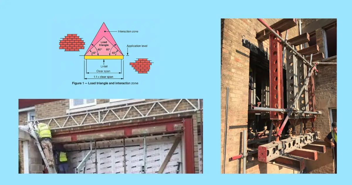
Careful structural assessment is vital to secure the safety and integrity of the building. BS 5977 has a useful guideline on how to consider loads around openings, as shown in the figure below.

Hence, a structural engineering professional must analyze the conditions of the structural elements, the type of structural systems, and how the load is transferred from upper elements down to the foundation(load paths).
The structural assessment is also necessary to decide whether the wall is load-bearing or not. It is also needed to ascertain how the structural system is transferring the loads so as to know which load transfers will be disrupted and to plan for supporting those load path disruptions.
Structural assessment of buildings for shoring
The method of shoring suitable for a project is also influenced by the type of building. The methods vary between brick, masonry, block, timber, and steel-framed buildings.
Although most methods apply to all types of buildings arching action of masonry is only considered in the structural assessment of masonry buildings.

The phenomenon of arching action during structural calculation relies on the condition that the wall is assessed to be arching over the opening. The arching action of the wall should be assessed, and if arching action is confirmed, then structural calculations, as shown above in Figure B, using the load triangle, can be considered.
If the arching action is absent, the load triangle calculation does not hold. For larger openings, the arching action is likely not enough; also, near the corners, there may not be enough masonry to result in arching actions. In these cases, the full loading above should be taken. For small openings (<0.5m), often any support is unnecessary because of the arching action.
The presence of the arching action can be checked by measuring the distance from the apex of the load triangle to the top of the location of the loads under consideration along the wall, as shown in Figure B. If the distance is at least 8 inches, considering no other limitation exists, the arching action can be considered. If the 8-inch is present, the lintel should be designed only for the dead load of the wall in the load triangle.
Otherwise, since the arch action is absent, the lintel needs to be designed for all gravity loads above the opening. So, checking if arching action is present is a major factor in designing openings in masonry walls.
When designing a lintel or beam that supports a load-bearing wall, the arching action of forces gives rise to the typical loading triangle spread by 45°, as shown on a beam/lintel is shown below in Figure C – all loading within that 45° load triangle is taken by the beam. The weight of the wall that is included in the calculations is only that which lies in the load triangle.
Additionally, half of any point load or distributed load within that 60° zone is carried by the beam too (this could be from a window opening or floor/roof load).

Types of Propping Solutions
Several established shoring methods exist, each suited to specific circumstances and structural conditions. The selection depends on wall composition, load magnitude, and project requirements.
1. No-more-prop proprietary solutions
These are prop-free solutions, best suited for small openings, small-scale projects, and upper-floor works. They are designed to maintain the existing load path with minimal disturbance
They offer a low-cost solution and are ideal when a localized approach is needed, especially in situations where the building components above and below should not be disturbed due to occupancy or access issues that prevent the installation of additional supports
1.1. Temporary lintels: No-More-Prop Solution
This is the simplest and the most cost-effective method of creating openings in load-bearing walls. The method is suitable for small openings (<2.5m) in walls up to 230mm thick. This method does not require multiple props, so it saves the cost of the support systems and also creates more space for access.
It is particularly useful for upper floor works since it does not require setting up props from the floor below to transfer the loads to the bottom floors. It enables work from one floor only.
The method is beneficial when setting up props from floors below is not possible, in cases such as
- A finished space,
- Inaccessible,
- Already supporting critical loads or delicate finishes.
Advantages:
- Faster and cleaner than traditional acrow props.
- Reduces on-site clutter and labor for propping.
Limitations:
- Not suitable for corners or areas near existing openings (where arching can’t develop).
- Best for small-scale, domestic applications (e.g., creating doorways or small windows).

1.2. Brick Brace System: No more prop solution
This system uses scaffold tubes with special clips inserted into the mortar joints. It operates on the principle of post-tensioning, where tightening bolts induce compression in the bricks. This enhances the arching action and ensures tthe emporary stability of the wall

– How it works:
– A scaffold tube runs horizontally above the opening.
– Special metal clips are inserted into the vertical mortar joints of the brickwork and connected to the tube.
– When bolts on the clips are tightened, internal plates splay outward, compressing the brickwork below and creating a pre-tensioned support.
-Bricks are strong in compression and the pretensioning creates compression on the bricks. It enhances the arching action and the structural integrity of the wall stays stable during the works.
– Once installed, the wall below can be removed safely while the system transfers loads to the sides.

Advantages:
– Minimal intrusion: No need for vertical props, keeping the workspace clear.
– Quick installation: Faster than traditional needling for small openings.
– Reusable: Components can be reused for multiple openings.
– it is suitable where limited space or access is limited.
-It does not require supporting floors below
–Stabilizes Weak or Lime Mortar Masonry: Particularly effective for older buildings with lime mortar, which is more prone to movement and failure25.
Limitations:
– domestic scale only(use in residential or small-scale buildings (houses, small extensions, etc.)
– Suitable for walls up to ~230mm thick(single-leaf brick or block).
– Less effective near corners or where mortar joints are weak.
– Load capacity: Lower than heavy-duty propping (e.g., strong boys or needle beams).
1.3. Strong Boys
.

Figure G- Strong boy system
Strong Boys are small but mighty props designed for supporting masonry above openings in load-bearing walls. They are typically used for Small-scale propping (350kg capacity). They consist of props and Steel plates that are inserted into the wall at regular centers of 600-900 mm c/c. They are used with cavity walls or single leaf walls.
How it works:
– Steel plates are inserted into cut slots in the masonry at regular intervals above the proposed opening
– Each plate connects to an adjustable prop (typically an Acrow or similar)
– The system supports the masonry while allowing space below for creating the new opening
Key features:
– Each prop head has a capacity of about 350kg
– Often Designed for walls up to 230mm thick (standard brick/block construction), however there are different standard sizes that can be used for larger wall thickness.
– Often used in combination with secondary props to reduce floor loading
Advantages:
– Space-saving: All props on one side leaves other side clear for access
– Adjustable: Can be fine-tuned to ensure proper support
– Versatile: Works on upper floors where foundation access is limited
Limitations:
– Low capacity: Not suitable for heavy loads or large openings
– Floor strength critical: Requires assessment of floor capacity below
– Bracing needed: Requires lateral stability measures
Special considerations:
– Always need load spreading(timber or metal beams) under props
– Must account for cumulative loads when used on multiple floors
– Foundation capacity must be verified, especially on suspended floors”
Comparison to Other Systems
Strong Boys fill the gap between:
– No-More-Prop/Brick Brace (smaller, simpler openings)
– Full needling (larger/heavier duty applications)
2. Traditional Needle sceme( called also Dead shoring)
Needling is one of the most versatile and commonly used techniques for supporting load-bearing walls during partial demolition. The technique is commonly applied to concrete, masonry and even timber and steel framing if the structural assessments recommend it as the best solution for the project. It is the go to solution for for thicker walls/heavier loads.
This method involves:
- Drilling/cutting openings through the wall at calculated intervals
- Inserting transverse beams (needles) through these openings
- Supporting the needles with vertical posts or adjustable shores on both sides of the wall
- Removing the part of the old walls where the new opening is to be constructed.
- Construction of the wood or steel structural beams that is to provide support of the wall above the opening
- Constructing stable support for the new beams that is to support the wall above the opening
This technique effectively transfers the load from above the planned opening to the supports alongside the wall. Needling is particularly suitable for creating new openings in load-bearing walls for doors, windows, or open-concept designs. The procedure should ideally be supervised by a professional engineer to ensure proper load calculations and implementation.
How It Works
1. Needle Beams:
– Steel beams (UB/UC sections or RSJs) are inserted horizontally through the wall though small openings at regular interval of 1-1.5m for masonry but depending on the wall material and the loads.
2. Vertical Props:
– Needles are supported by adjustable props (Acrows, telescopic props, or scaffold towers) on both sides of the wall.
– Props transfer loads to stable foundations (ground-bearing or back-propped to lower floors).
3. Load Path:
– Wall loads → Needles → Props → Foundations.
– The 45° load triangle (from beam theory) determines how much masonry the needles must support.
4. After lintels are installed the loads are transferred from the lintels
-To Bearing Points (Supports) at Each End
-Vertically Through Load Paths in the Wall(masnonry below, column postsVia Padstones (for High Loads),)
-Arching Action (Masonry Lintels)
-Composite Action (in Cavity Wall Lintels or Box Lintels)
Advantages
✅ Suitable for For Heavy Loads:
– Handles thick walls (concrete, stone, or multi-leaf masonry).
– Supports high floor/roof loads above openings.
✅ Adjustable:
– Props can be fine-tuned to compensate for settlement.
✅ Buildability:
– Leaves a clear workspace below for demolition/construction.

3. Reverse Needling, also called balanced needle scheme
Reverse needling scheme is an alternative to the traditional needling scheme that is useful for weak floors. It alienates the loads from the floors and maintains the original load path and transfers the Load down, then back into the wall below.
When working with weak or suspended floors where traditional propping isn’t feasible, reverse needling provides an elegant load-path solution that bypasses problematic structures.

How It Works
1. It redirects the loads upward via needles to an upper needle support instead of propping downward to weak floors. The load is then transferred laterally back into sound wall sections, avoiding the weak floors. It creates a “load loop” that avoids overloading intermediate floors
2. Key Components:
– Upper needles: Steel beams supporting masonry above opening
– Vertical props: Transfer load upward to stable structure
– Lower needles: Redistribute loads back into solid wall below
3. Load Path:
Wall Loads → Upper Needles → Vertical Props → Lower Needles → Sound Wall Sections
Advantages
✔️ Weak floor scenarios:
– Timber floors
– Slender concrete slabs
– Vaulted ceilings below
✔️ Access constraints:
– When lower floors are occupied/restricted
– Historic buildings with delicate finishes
✔️ Multi-story propping
– Avoids “prop towers” through multiple levels

4. Temporary Support Walls
For timber houses, temporary support walls constructed parallel to the load-bearing wall are a practical solution.
A typical temporary wall construction involves the following steps.
- Creating a temporary wall with angled 2x4s or 2×10 alongside the existing wall
- Installing top and bottom plates screwed to the ceiling and floor
- Wedging 2×4 or 2×10 studs that are slightly longer than the distance between the plates into position
- Securing the first and last studs with nails through their bases9
This approach is efficient for installing headers for new windows or doors in bearing walls. While this technique uses minimal materials and requires less installation effort, every stud should be properly fastened top and bottom to prevent accidental dislodging.

5. Confinement Shoring Method
This is a type of no-prop solution. For situations where wall stability is particularly critical, the confinement method provides enhanced safety. This method is suitable when the crew is not very experienced, if extra safety is needed. This technique involves:
- Placing beams on both sides of the wall
- Connecting them with epoxy-coated threaded bars through the wall
- Creating a unified support system that confines the wall material

This approach is especially valuable when the renovation crew may not be highly specialized in structural modifications, as it provides greater safety margins. While typically suitable for lower loads, it has the advantage of not requiring temporary lowering of the wall during installation7.
6. Pin & Stool(Pynford scheme) Method
This method Cast Cast-in-situ beam intel, is installed using steel stools for temporary support during installation. It offers A precision technique for creating openings by casting an in-situ concrete beam within the wall itself – ideal when minimal disruption is critical.
Best For:
– Thick masonry/concrete walls (>300mm )
– Sensitive structures where vibration must be avoided
– Projects requiring high load capacity
Step-by-Step Process
1. Pocket Formation:
– Carefully cut/drill pockets at lintel locations
– Typical spacing: 1-1.5m for masonry walls
2. Stool Installation:
– Insert and dry-pack steel or precast concrete stools with non-shrink grout
– Verify full bearing before proceeding
3. Channel Creation:
– Form horizontal slot between stools
– Install reinforcement cage
4. Concrete Pour:
– Use high-flow mix (often SCC) to ensure compaction
– Vibrate carefully if permitted
5. Curing & Demolition:
– Allow 7-28 days curing (depending on design)
– Remove the wall below only after full strength is achieved

source: thestructuralengineer.org
7. PFC (Parallel Flange Channel) Method
Installation Sequence
1. Wall Preparation:
- break up pockets in the brick on one side only.
- After installing the stools, we create a slot in the wall and install the lintel
– Drill holes for tie rods at designed centers (usually 600-1200mm)
– Clean voids to ensure rod alignment
2. Channel Installation:
– Hoist PFCs into position either side of wall
– Temporarily brace channels plumb
3. Connect PFC channels by bolting:
4. Demolition & Permanent Works:
– Remove wall material between channels
– Install permanent beam/lintel
– Gradually release rod tension after the new support is active

5. Scissor Propping
An innovative Single-sided support solution for complex load transfer where traditional vertical propping isn’t feasible, using a combination of props and ties to create a self-stabilizing system.”*
This solution solves access problems, for instance where only one side is needed for access to allow other works on the other side. It also allows the load pathe be not altered which is important in case the floor is weak.

The mechanism uses cantilevered needles with tension ties to form a balanced “scissor” load path
It Solves challenges with:
– Uneven floor levels
– Limited foundation access
– Asymmetrical loading
– Typical Applications:
– Lift shaft installations
– Mezzanine openings
– Heritage structures with access restrictions
Key Components
1. Upper Needle:
– Steel beam (UB/UC) cantilevering into wall
– Designed for bending + shear
2. Lower Needle:
– Counter-balancing beam below opening
– Often incorporates permanent works
3. Tension System:
– High-strength rods or flats
– Prevents uplift at prop bases
4. Lateral Bracing:
– Diagonal members preventing sway
– Typically 50x50mm SHS or proprietary bracing
Load Path
Wall Load → Upper Needle → Compression Props → Lower Needle → Tension Tie → Sound Structure
Factors to consider in creating an opening in load-bearing walls
Preliminary Assessment and Planning
Before any demolition or shoring work begins, a thorough structural assessment is essential to develop an effective strategy. Creating openings in load-bearing walls is highly risky work that can result in permanent damage if it is not conducted carefully.
This initial phase is critical for safety and project success. According to ASCE 37, BS 5975, and CDM 2015, it is recommended that a competent engineer be consulted for the planning and designing of the shoring in order to ascertain that the structure meets safety and functional requirements.
Project characteristics that should be considered:
Services in the walls
Exclusion zones
Foundation requirements for props
Lateral stability of temporary works and surrounding structures
New beam installation method
Possibility of permanent works Integration
Allowable deflections
Overall stability responsibility
Buildability and safety (ERIC principles,UK)
Site Conditions Evaluation
It is absolutely critical to know about the structure and its behaviours beforehand as the quality and success of interventions depends entirely on it. Site conditions play a significant role in determining the most appropriate shoring strategy.
Factors including available workspace, access points, floor condition, and adjacent structures must be assessed. Limited space may restrict the use of certain shoring methods, while the condition of the supporting floor will determine the need for load distribution platforms.
A proper site investigation is essential to understand the existing structural behavior before any modification of load-bearing elements.
Identifying the type of structure and material
Initial assessments will identify the type of building structure, the type of structural system, and the material type of the parts of the building. The planning of the type of shoring support depends on the type of building. If it is masonry, then arching action and load triangles come into application. If the building is timber or steel, other suitable shoring systems are considered.
Structural Load Analysis
A comprehensive evaluation of the loads supported by the wall is the first crucial step in any shoring project. This analysis must consider dead loads, live loads, and any potential lateral forces that may affect the structure. This will help in identifying the load paths that can be potentially disturbed and need support.
According to professional practice, understanding load distribution and structural support mechanisms is fundamental before modifying any load-bearing elements. The magnitude of loads will directly influence the type of shoring system required and its implementation.
Ensuring sound lateral stability should be ascertained at all times. Before wall removal, consider the lateral stability of both the propping and the wall itself. Don’t forget that adjacent floors may need support.
Design Documentation and Approvals
Professional engineers often debate whether detailed shoring designs should be included in renovation plans or left to contractors as “means and methods.” While some engineers simply state “provide shoring as required” on plans, others request contractor-supplied shoring designs sealed by a professional engineer for approval.
For complex projects involving significant load-bearing wall removal, such as a 100-foot section supporting bar joists, having professionally designed and approved shoring plans is highly recommended. Since creating openings in load bearing walls most of the time requires regulatory permits, it is necessary to inquire to the regulatory body of the region whether it is necessary.
Professional Oversight and Qualification
The complexity of load-bearing wall modifications demands appropriate expertise:
- Qualified structural engineers should design or approve shoring systems
- Experienced contractors specialized in structural modifications should execute the work
- Regular inspection during implementation should verify adherence to design specifications
Comprehensive Load Transfer Verification
Before removing any portion of the load-bearing wall, the shoring system must be verified to effectively support all loads:
- Ensuring all shoring components are properly installed and secured
- Verifying that the system is level and properly tensioned
- Confirming that loads are effectively transferred to the temporary supports
Only after this verification should any demolition work begin. It is necessary to use adjustable components like U-heads on shoring towers which allows for precise leveling to ensure proper load distribution.
Careful Execution Sequence
The sequence of operations significantly impacts project safety. The Construction Sequence in all of project life should be considered in the design carefully.
Consider worst-case loading during the entire design life (plant, materials, snow, etc.) and how loads transfer back to permanent works.
The construction sequence follows:-
- Complete installation and verification of the entire shoring system
- Begin demolition only after shoring is fully operational
- Install permanent structural elements (beams, columns, lintels) while shoring remains in place
- Remove shoring only after new permanent supports are fully installed and secured
This methodical approach ensures continuous structural support throughout the renovation process, minimizing risks associated with load-bearing wall modifications.
Safety Considerations and Risk Management
Safety must remain the paramount concern throughout any shoring operation. Several critical considerations should guide all aspects of the project.
Structural Monitoring
Continuous monitoring of the structure during modification is essential:
- Observing for any signs of unexpected movement or stress
- Monitoring key indicators such as cracks, deflection, or settlement
- Having contingency plans for immediate additional support if needed
This vigilance allows for prompt intervention if the structure behaves differently than anticipated during the modification process.
Load Path Protection
Understanding and maintaining load paths throughout the renovation is critical:
- Ensuring loads are always supported by either the original structure or temporary supports
- Avoiding disruption of load paths during transitions between support systems
- Verifying that temporary and permanent load paths have adequate capacity
Professional practice emphasizes the importance of evaluating “modifications that may exist at the entire height of the wall where intervention is made” to ensure complete load path protection.
Worker Safety Protocols
Beyond structural considerations, worker safety requires specific protocols:
- Providing clear instructions about safe work zones
- Establishing communication procedures during critical operations
- Ensuring all personnel understand the shoring system and its limitations
The optimal strategy for shoring a structure during partial demolition of a load-bearing wall combines thorough assessment, appropriate technique selection, professional implementation, and rigorous safety protocols. No single approach suits all situations, as the ideal strategy depends on multiple factors, including load magnitude, wall composition, available space, and project requirements.
For most renovation projects, a professional needling and propping system designed by a qualified structural engineer according to relevant standards and regulations offers the best balance of safety, effectiveness, and efficiency.
The table summarizes the key standards for temporary works and structural modifications (such as creating openings in load-bearing walls):
| Standard/Code | Region/Body | Scope/Description |
| BS 5975 | UK/BSI | Temporary works procedures and permissible stress design |
| ASCE 37 | US/ASCE | Design loads on structures during construction |
| EN 1991-1-6 | EU/CEN | Eurocode for actions during execution (temporary loads) |
| ASCE 7 | US/ASCE | Minimum design loads for buildings (permanent loads) |
| CSA S269.1 | Canada/CSA | Falsework for construction purposes |
| NZS 3910 | New Zealand/SNZ | Temporary works and construction procedures |
| DIN 4420 | Germany/DIN | Scaffolding and temporary works |
| AISC Specifications | US/AISC | Steel construction, temporary bracing and shoring |
Sources-
- https://www.youtube.com/watch?v=LKI1vQl8u9M
- https://www.eng-tips.com/threads/what-is-the-best-strategy-for-shoring-a-structure-during-the-partial-demolition-of-a-load-bearing-wall-in-a-renovation-project.527461/
- https://www.andun.co.uk/types-temporary-works-used-for-demolition-projects/
- https://www.eng-tips.com/threads/shoring-cmu-walls.172355/
- https://robore.com/cut-carve-demolition/
- https://www.kreo.net/glossary/needle-beam
- https://www.kaitekarquitectura.com/en/remove-a-load-bearing-wall/
- https://fortuneluxuryhomes.com/2022/01/23/what-is-needling-or-propping-in-construction%EF%BF%BC/
- https://www.finehomebuilding.com/readerproject/2011/01/31/shoring-up-a-load-bearing-wall
- https://www.siteequipment.co.uk/insights/propping-and-needling-in-action/