
Early railway tracks were constructed mostly as ballasted railway tracks. The speed of the trains was low so the ballasted tracks have been performing well. However, as the speed of trains became higher the use of more efficient railway tracks was sought after. That led in the 1970s to the first application of ballastless track.
The design of the track system of railways should meet the structural, operational, economic, and environmental aspects of the project. The track systems that are nowadays in use are ballasted railway tracks and ballastless, or slab railway tracks.
What is a ballasted railway track?
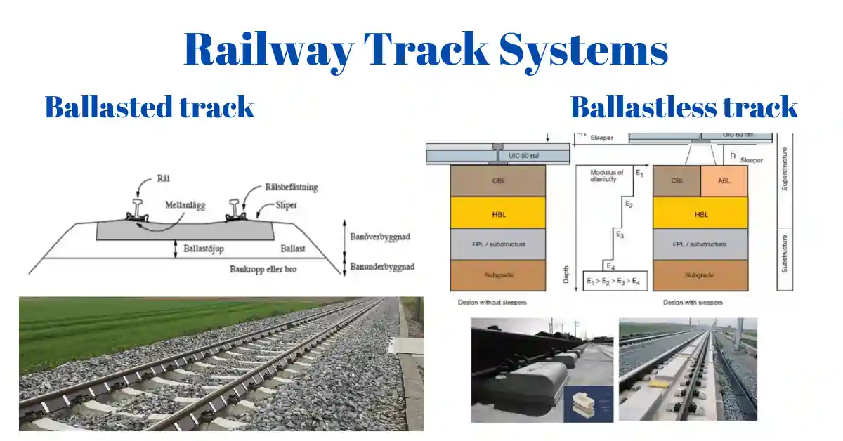
Ballast railway tracks consist of a series of parallel rails supported by wooden or concrete sleepers, which are laid on a bed of crushed stone or gravel called ballast. The ballast provides stability, drainage, and support to the tracks, helping distribute the weight of the trains evenly and preventing the rails from shifting.
The components of ballast railway tracks are covered in detail in our articles Exploring Railway Track Components: Rails, Fastenings, Sleepers, and Turnouts – Civil Engineering Tech (civengtech.com) and Railway formation, substructure and superstructure – Civil Engineering Tech (civengtech.com)
The materials included in a ballasted track are:
– Ballast
– Concrete sleepers
-Fastening systems
– Steel rails
– Polyamide isolators
– Neoprene elastomer pads.

Ballasted track structure consists of superstructure and substructure as follows: (from top-down):
– Track superstructure:
• Rails,
• Fastening of the rails to the rail support,
• Rail support (sleepers),
• Ballast,
• Sub-ballast,
– Track substructure:
• Formation Layer (Sand Blanket),
• Subgrade,
• Subsoil.
What is a ballastless or slab track system?
Ballastless or slab railway tracks are a modern type of track construction where the rails are directly mounted onto a solid concrete slab or solid concrete modules without using traditional ballast. Rarely, slab tracks can also use asphalt surfaces instead of concrete surfaces.
Their common use started in 1970 even though the first slab tracks appeared at the beginning of the 20th century. Their application became more attractive for high-speed lines (300km/h) because of their structural stability, longer life cycles, and lower maintenance needs. Mainly they are implemented in high-speed or light rail lines.
The materials included in a typical slab track, are: –
-Concrete slab
-Fastenings
– Neoprene elastomer pads.
-Steel rails
– Polyamide isolators
Slab track structure consists of superstructure and substructure as follows (from top-down) :
– Track superstructure:
• Rails,
• Fastening of the rails to the rail support,
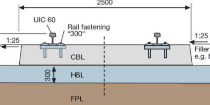
• Rail support (sleepers, single supporting points, pre-fabricated or monolithic slab),
• Concrete-bounded foundation layer (CBL) or asphalt-bounded foundation layer (ABL) depending on the use of sleepers,
• Hydraulically bonded foundation layer (HBL),
– Track substructure (if slab track construction is built on earthworks):
• Frost protective layer (FPL),
• Subsoil layers (consolidated or improved material of earthworks in the embankment or earthen cut),
• Consolidated soil or bedrock

This design offers advantages such as reduced maintenance, increased stability, smoother rides, and improved resistance to weather and environmental factors. The absence of ballast also eliminates issues like ballast degradation and track settlement, making ballastless tracks suitable for high-speed and heavy-load rail systems.
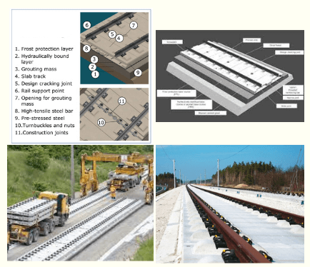
The bearing layers of slab track systems
The bearing layers consist of a concrete or asphalt bearing layer, a Hydraulically bonded bearing layer, a Frost protection layer, and a subgrade.

Concrete Bearing Layer:
The concrete bearing layer must adhere to strict standards, including a profile tolerance of ±2 mm and a minimum thickness of 180mm to withstand bending loads. Reinforcement, typically longitudinal ϕ20/20 and lateral ϕ16/40, helps limit crack formation, ensuring durability. It requires a minimum resistance to pressure of 12 N/mm² and may include controlled crack formation points every 2 meters. Laying involves a finisher, with reinforcement typically placed at the slab’s center.
Asphalt Bearing Layer:
The asphalt bearing layer, applied in four layers totaling 300mm, maintains a surface tolerance of ±2 mm and operates efficiently in temperatures below 50°C. To mitigate UV sensitivity, protective measures such as stone chip spreading are necessary. Laying involves precise construction methods to ensure durability and performance.
Hydraulically Bonded Bearing Layer:
The hydraulically bonded bearing layer, crucial for enhancing total bearing capacity, consists of mineral aggregates and Portland cement as a bonding agent. A mix of mineral aggregates is used like sandstone, crushed sand, and stone chips. The maximum grain size should not exceed 32 mm. With a typical thickness of 300mm, it’s laid in two layers of at least 12cm each, forming pseudo joints every 5 meters to control cracking. The layer’s edges are inclined outward by at least 4% to prevent water infiltration. It contributes to achieving a modulus of deformation of ??2 ≥ 120 N/mm² on the frost protection layer.
Frost Protection Layer:
The frost protection layer serves to shield upper layers from frost and can be used to swiftly divert surface water away. Composed of fine gravel with low permeability it can prevent water from rising from the subsoil. it must exhibit high resistance to weathering and frost. Achieving a modulus of deformation of ??2 ≥ 120 N/mm² requires meticulous material selection and construction techniques, similar to those used for the hydraulically bonded bearing layer.
Factors Considered in the Design of Slab Tracks
The successful design of slab tracks relies on careful consideration of several key factors.
1. Load-Bearing Capacity:
Slab tracks must support the weight of trains, passengers, and cargo efficiently. Engineers analyze factors such as axle loads, train speeds, and traffic volume to determine the appropriate load-bearing capacity required for the slab track design.
Slab track systems offer greater stiffness compared to ballasted tracks, necessitating subsoils with minimal deformation and settlements due to their lower adaptability to settlements. While ballasted tracks can tolerate settlements up to 2 cm over 10 meters and adjust easily, slab tracks face limitations in adjusting track geometry post-construction.
Earthworks for ballasted tracks require a substructure depth of 0.5 m below the frost protective layer, whereas slab tracks demand a depth of at least 2.5 m below the foundation surface, posing a challenge for designers. Despite higher construction and material costs, well-designed slab tracks promise extended lifetimes and reduced maintenance expenses.
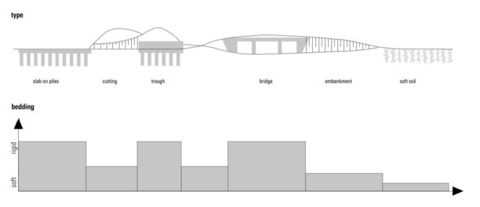
Ensuring seamless transitions between slab track segments and various vertical bedding modules, such as rigid bridges to soft earthwork constructions, is crucial as it represents a significant discontinuity in the path without ballast. In addressing soft soil conditions, methods like soil compaction or the use of CFG columns offer viable solutions to improve the subgrade without resorting to costly reinforced piles.
In situations where conventional measures prove impractical or prohibitively expensive, designing the slab track on piles becomes necessary to mitigate long-term settlement and unpredictable consolidation behavior. This design entails supporting the track’s superstructure with a reinforced concrete slab directly on piles, effectively distributing loads and eliminating the impact of unstable subsoil as filling material. This approach ensures minimal settlement and provides a rigid construction independent of sub-grade soil quality, akin to bridge construction in terms of settlement and stiffness.
2. Subgrade Conditions:
The condition of the subgrade, the layer of soil or material beneath the track, significantly influences slab track design. The choice of using discrete or continuous rail track support is most influenced by the subgrade soil conditions. Engineers assess soil properties, and bearing capacity, to ensure proper support and stability of the slab track structure. When the underlying soil is weak or soft, a slab track system with high flexural stiffness is required to act as a bridge across weaker points and local deformations in the substructure
3. Thermal Expansion and Contraction:
Temperature variations can cause concrete slabs to expand and contract, leading to cracking and deformation if not adequately addressed. Designers incorporate expansion joints, insulation materials, and reinforcement techniques to accommodate thermal movements and prevent structural damage.
4. Drainage:
Proper drainage is essential to prevent water accumulation beneath the slab track, which can weaken the subgrade and compromise track stability.

Ballasted tracks utilize separated sleepers, unbound bearing layers, and transversal slopes to direct water to parallel culverts.
However, the drainage of slab tracks can require additional channel drainage construction. Engineers design drainage systems, including channels, pipes, and permeable materials, to effectively manage water runoff and maintain track integrity.
5. Noise and Vibration Control:
Ballasted tracks have lower noise and vibration compared to slab track systems. The reason is the uncoupling of the rail fastening and the lack of noise absorption of the ballast bed.
However, modern slab tracks offer superior noise and vibration attenuation because of the effective use of vibration dampers and noise prevention systems.
Design considerations such as resilient materials, damping layers, and track alignment help minimize noise and vibration levels, contributing to a quieter and more comfortable railway environment.
6. Location of the slab track
The location of the track can influence the choice of slab track design. For instance, the location of a bridge, or tunnel is prone to dynamic forces that, may require slab tracks with special designs. The construction of bridges and tunnels has a stable and firm foundation to lay the slabs directly but the forces on bridges and drainage issues in tunnels require consideration.

6. Construction and Maintenance Costs:
While slab tracks offer long-term cost savings due to reduced maintenance requirements, initial construction costs can be higher. Engineers evaluate construction methods, material choices, and maintenance strategies to optimize lifecycle costs while ensuring quality and reliability.
7. Environmental Impact and passenger comfort:
Sustainable design practices are increasingly prioritized in slab track projects. Engineers explore eco-friendly materials, energy-efficient construction techniques, and wildlife mitigation measures to minimize environmental impact and promote long-term sustainability. The desired comfort for passengers may need a particular type of slab track over others.
The design of slab tracks involves a comprehensive evaluation of various factors, including load-bearing capacity, subgrade conditions, thermal considerations, drainage, noise and vibration control, construction and maintenance costs, and environmental impact. By addressing these factors systematically, engineers can develop robust and efficient slab track solutions that meet the demands of modern railway infrastructure while enhancing passenger experience and minimizing environmental footprint.
Components of ballastless or slab track systems
The components of ballastless or slab track systems typically include:
1. Concrete Slab: A solid concrete foundation onto which the rails are directly mounted.
2. Rail Fastening Systems: Mechanisms used to secure the rails to the concrete slab, ensuring proper alignment and stability.
3. Rail: The steel rails that provide the running surface for trains.
4. Sleepers or Support Elements: Concrete or composite supports that help distribute the load from the rails to the concrete slab.
5. Insulation Layers: Materials used to dampen vibrations and reduce noise transmission between the rails and the concrete slab.
6. Drainage Systems: Channels or pipes integrated into the track structure to manage water runoff and prevent waterlogging.
7. Expansion Joints: Flexible connections are installed at intervals to accommodate thermal expansion and contraction of the concrete slab.
8. Transition Zones: The transition zone between ballasted and ballastless tracks is accompanied by a change in the stiffness of the track. To compensate for the effects of the abrupt change in stiffness, often it requires a specialized design to ensure smooth transitions.
The transitions are made smoother by compensating the stiffness changes adjusting the stiffness of fastening or adding extra rail or auxiliary rails. The use of soil stabilization or use of geo-piers (stone columns, concrete piles, sand, and timber columns) are effective subgrade strengthening methods.
These components work together to provide a durable, stable, and low-maintenance track system suitable for various railway applications.
Types of slab or Ballastless Track Systems
Ballastless or slab track systems have varying design types because their design originates from many countries and have different purposes.

Generally, the designs are categorized into discrete and continuous rail support systems. The types of designs vary based on:-
-Construction without sleepless or with sleepers,
-Casted in situ or prefabricated
– Fasteners casted integrated with concrete slab or prefabricated concrete,
-Block modules or sleepers placed in prepared slots in concrete slab
-Rails embedded in slab or fixed with clamps.

Discrete rail support slab tracks and continuous rail support slab tracks employ distinct design approaches tailored to their respective structural configurations and operational requirements. Whether utilizing modular precast elements or monolithic construction techniques, designers prioritize factors such as track alignment, stability, resilience, and maintenance efficiency to deliver safe, reliable, and cost-effective slab track solutions.

Ballastless track systems revolutionize railway infrastructure by eliminating traditional ballast beds. They offer enhanced durability, reduced maintenance, and improved track stability. These systems can be categorized based on their support structures and installation methods.
Discrete Rail Support
In discrete rail support systems, the continuous rail is fixed on supporting points (usually fastened on sleepers or without sleepers). The individual sleepers or blocks are encased in concrete or placed on the concrete surface. In sleepless designs, the rails are directly fastened to the concrete surface.
Design with sleepers
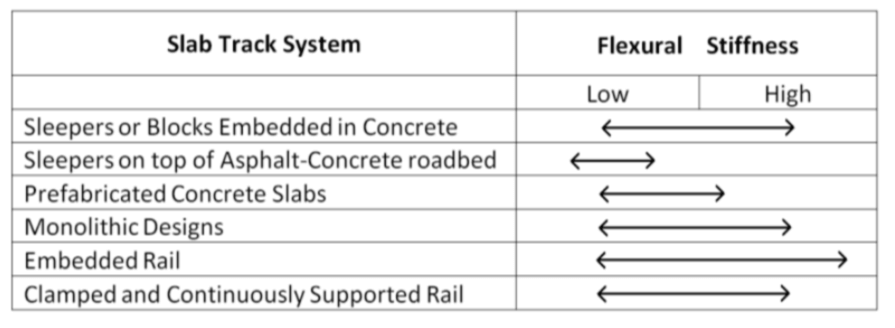
With Sleepers or Blocks encased in Concrete
In this configuration, sleepers or blocks are encased or casted in concrete for added strength and stability. This design approach combines the benefits of traditional sleeper-based tracks with the durability of concrete structures. Sleepers or blocks encased in concrete offer excellent load-bearing capacity and resistance to wear, making them suitable for high-traffic railway corridors.
A prominent design is the rheda system which is most widely adopted worldwide and exists in various structural designs and specifications. The Rheda system consists of monoblock or dual block sleepers that are casted monolithically and continuously reinforced in the concrete slab.


The other system that is used widely is the Zublin system. This system is adopted to increase production and it consists of dual or monoblock sleepers that are casted monolithically in concrete without continuous reinforcement. The difference with the latest Rheda 2000 system is it requires special machinery for installation. However, requires lower labor costs, and a 200 m track can be installed in 8 hours using machinery.

The Stedef, Wallo, and Sonnevile-LVT(low vibration track) systems are slab track systems with similar construction and design principles. These systems, originating from France and Switzerland, utilize a resilient pad placed beneath the sleeper.

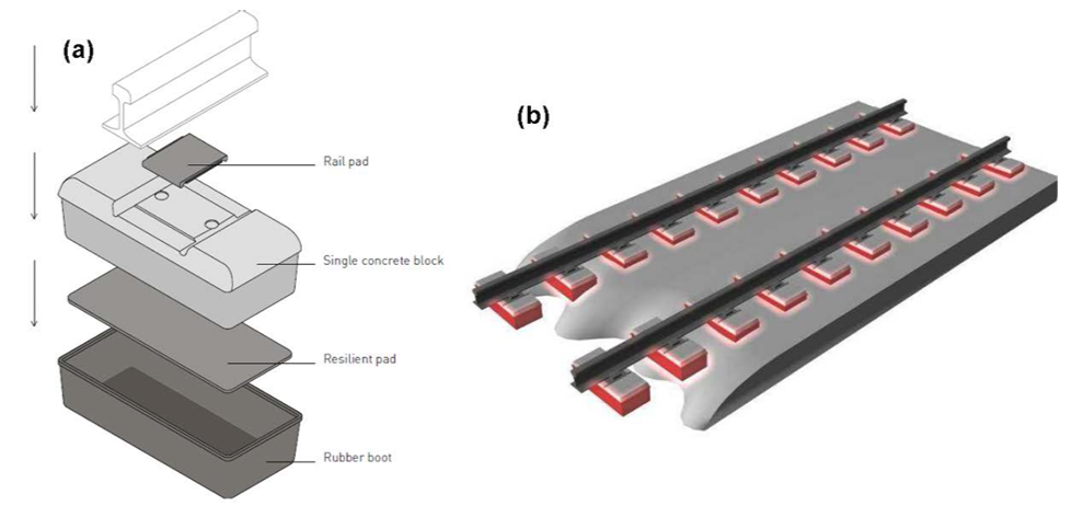
This resilient pad is then enclosed in a rubber boot, offering significant flexibility and effectively reducing noise and vibrations. This design ensures high protection against environmental disturbances while maintaining track stability.

Sleepers on Top of Asphalt-Concrete Roadbed
This design places sleepers directly on top of an asphalt-concrete roadbed, providing a stable foundation for the track that can serve as an alternative to ballast. The asphalt properties can fulfill the plastic properties that may be needed. The roadbed offers uniform support and disperses loads effectively, reducing track deformation and enhancing overall track performance. Sleepers on top of asphalt-concrete roadbeds are commonly used in urban areas and high-speed rail lines.
A particular application of this approach to design is the ATD system which features an asphalt roadbed over a cement-stabilized support layer, with sleepers placed atop the asphalt and a ridge between them absorbing lateral forces. win-block or mono-block sleepers equipped with grooves are utilized to resist lateral forces. Basic elements of the ATD system include the Hydraulically-bonded Layer (HBL), Asphalt Supportive Layer (ABL or ASL), twin-block or mono-block sleepers, and elastic rail fastenings with UIC 60 rail.

Sleeperless designs
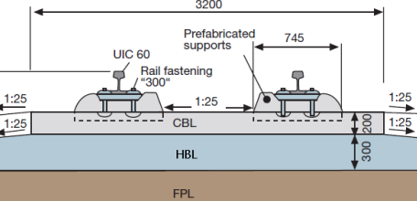
Prefabricated Concrete Slabs
Prefabricated concrete slabs are reinforced or prestressed concrete slabs precast off-site and installed as complete units along the track alignment. These slabs offer precise constant inclinement and guage of the rails simultaneously.
These slabs offer rapid installation, consistent quality, and reduced construction time compared to traditional construction methods. Prefabricated concrete slabs ensure precise track alignment and require minimal maintenance, making them an efficient choice for modern railway projects. However, they can result in higher expenditure.
A prefabricated concrete track system that has been used since the 1970s in Japanese high-speed railway is The Shinkansen slab track system. It consists of a continuous concrete slab with embedded rail fastenings casted in the concrete slab, providing excellent stability and ride quality. This track system has concrete cylinders(dowel) that hold the slabs longitudinally and laterally which are rigidly connected with the structural concrete of the bearing plate.


The Bögl slab track system is another product developed in Germany in 1977. It features prefabricated steel fiber concrete plates measuring 20cm thick, 6.45m long, and 2.55 or 2.80m wide, with a total construction depth of 475mm. These plates are laterally prestressed and longitudinally reinforced with GEWI bars, featuring special breaking points between supporting points to prevent random crack formation. The design resembles a system of wide sleepers joined together, with integrated screw-jacks allowing for easy and fast adjustment of the plates.

The other prefabricated slab track system called ÖBB-Porr was developed in Austria. The ÖBB-Porr system features slabs on elastic support with resilient fastening systems, initially tested in a 450m track in 1989. These slabs, measuring 5.16m × 2.4m × 0.16 to 0.24m, are adjusted on a hydraulically bonded bearing layer or concrete tunnel sole using spindles and sealed by concrete.

The system incorporates rectangular openings in the slabs for wedging mortar and horizontal force absorption, with surfaces coated in a resilient polyurethane-cement layer for vibration decoupling. A conical concrete plug is applied to prevent slab uplifting, ensuring ease of replacement and offering advantages against vibrations, creating a mass-and-spring system with a mass of 1 ton per linear meter.


Monolithic Designs
The designs mentioned consist solely of a continuous monolithic concrete layer with direct rail fastenings adjusted on it, eliminating the need for traditional sleepers. These sleeperless designs are constructed cast in situ monolithically by concrete pavers or as prefabricated slabs connected together.
Direct rail fastenings have the advantages of reducing weight, particularly at bridges and addressing sleeper-related issues. The monolithic designs exhibit stiffness and rigidity, behaving structurally as continuous supported elastic beams under traffic loading, making them suitable for soft soils. However, attention must be given to prevent crack formation in the concrete bearing layer due to rail fastenings, necessitating proper preventive measures.
The Lawn track(RASENGLEIS) system features a water-permeable concrete slab 30 cm thick, supported by two longitudinal reinforced concrete beams of trapezoidal shape. These beams are connected to a concrete bearing layer, ensuring track stability.
Rail fastenings are fastened to the beams using rail clamps while anchoring ties anchor the beams to the supporting layer. An environmentally acceptable and green track solution is provided by the substrate covered in oligotrophic grass that fills the space between the beams and their surrounding sections.

FFC (Feste Fahrbahn Crailsheim) slab tracks are renowned for their exacting manufacturing and installation procedures. The rail fastening system’s supporting points, or dowels, are either cemented into dried concrete slabs in predrilled holes or put into freshly poured concrete
The rail fastening system, IOARV300, is integrated into the concrete bearing layer during manufacturing, with adjustments made by a specialized machine. The concrete base is typically 2.4 meters wide but can extend up to 3.2 meters, with notches made every third support point to control crack formation and facilitate water runoff.

The Hochtief system features a concrete bearing layer (CBL) placed over a hydraulically bonded layer (HBL), with concrete-embedded rail support points for rail fastening. Each support point is secured with four linking anchors embedded into fresh concrete and adjusted for precise leveling and height alignment using a setting frame. Steel fiber concrete segments minimize visible cracking, while the surface of the CBL is inclined to facilitate rainwater drainage.
The BES slab track system comprises a reinforced concrete bearing layer (CBL) supported by individual points over a cement-stabilized layer (HBL). Developed in Germany, it shares a production process with the FFC system for rail fastenings. During installation, rail screw plugs are glued into pre-drilled holes in the dried concrete supportive layer. This design ensures stability and durability while facilitating efficient installation and maintenance processes.
Continuous Rail Support
Continuous rail support systems provide uninterrupted elastic support for the rails along the entire track length. The load is supported by embedded or clamped supports to the underlying concrete support layer. These systems offer superior stability, reduced maintenance, and enhanced ride comfort compared to discrete support systems. Continuous rail support systems can be further classified based on their structural designs and installation methods.
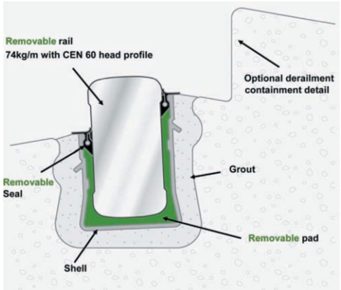
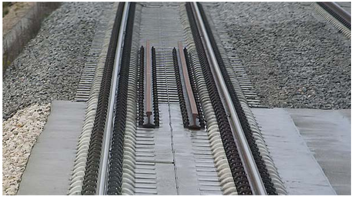
Embedded Rail Structure (ERS)
ERS systems embed the rails directly into the track structure, on elastic supports made of cork or polystyrene material. These configurations eliminate the need for separate sleepers or supports. This design optimizes load distribution, reduces noise and vibration, and enhances track resilience. These systems feature design with an absence of additional components to secure track gauge.ERS systems are commonly used in high-speed rail networks and urban transit systems.
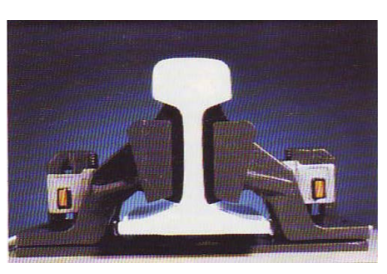
The key features of a rail fixation system:
1. Continuous Support: An elastic strip offers continuous support beneath the rail, ensuring consistent stability and minimizing vibrations.
2. Guided Rail: The rail is guided within a groove by elastic fixation, enhancing alignment and reducing lateral movement.
3. Top-Down Alignment: Alignment of the rail is achieved from the top-down perspective, allowing for precise adjustments and maintenance.
4. Fixed Rail Profile: The rail profile is secured in place by an elastic compound, maintaining its shape and integrity.
5. Optimization: Elastic compounds, groove dimensions, and strips are optimized to specific elasticity requirements, maximizing performance and durability.
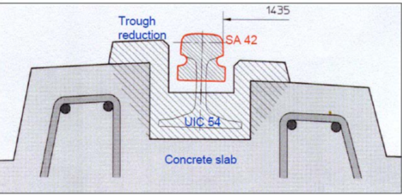
The INFUNDO and EDILON designs are systems in this category that share similar construction characteristics and principles, with INFUNDO being a further development of the Dutch Edilon design.
Originating in the Netherlands in the 1970s, INFUNDO is continuously supported by elastic compounds in a groove, with a concrete supportive layer laid by a slip-form paver. Intended mainly for urban passenger rails like subways and tramways,
INFUNDO compensates horizontal and vertical forces with a cork underpad and elastic components surrounding the rail. A precisely constructed concrete groove determines rail height, direction, gauge, and tilting. After drying, a U-shaped steel profile is inserted to encase the underpad, rail, and elastic components.
Advantages include reduced rail wear, low noise emissions, minimal components, fast construction, and suitability for combined surfaces.
A recent development introduced a lower-noise design by replacing the UIC 54 rail with the SA 42 rail, resulting in reduced noise levels and less polyurethane usage.

The BBERS (Balfour Beatty Elastic Rail System) is a type in this category that was developed in 2000 and first installed in Medina el Campo, Spain, in 2002. It shares construction principles with INFUNDO but utilizes a smaller rectangular rail (BB14072) and different rail elastic support elements.
The system employs a U-shaped continuous pultruded glass-reinforced plastic shell and a U-shaped pad made of microcellular polyurethane to accommodate the rail. Installation involves permanently placing the plastic box in the concrete trough, grouting the base of the shell, and then inserting the pad and rail.

The construction of BBERS can be carried out through three methods: slip forming, precast concrete slabs, and cast in situ. Slip forming involves preparing the formation, slip forming the slab, aligning and fixing the subsystem, and distributing and installing the rails.
Precast concrete slabs entail laying slabs, aligning and grouting them, joining slabs, and installing rails. Cast in-situ construction includes preparing the formation, pouring concrete, erecting shuttering, aligning and fixing the subsystem, grouting the shell, and distributing and installing the rails.

Clamped and Continuously Supported Rail
In this configuration, the rails are clamped onto continuous supports that provide consistent alignment and load distribution. Clamped and continuously supported rail systems offer excellent track stability and performance, particularly in curves and transitions. These systems ensure smooth and reliable rail operations, even under high-speed and heavy-traffic conditions.
The Cocon Track system, specifically designed for tramways, features a unique combined transverse and longitudinal concrete sleeper with conventional fasteners supporting the rail. Fasteners are strategically placed on the crossings of the H-shaped sleeper, with a distance of 1200 mm between them, suitable for curves with a radius greater than 20 m.
The system incorporates a two-layer strip beneath the rail, with the first layer being soft and compressible upon fastening, while the second layer provides stiffness to withstand loads. Additionally, a cork/rubber elastomer is applied between the fastener springs and rails to prevent direct contact, while the rail is encased in a high-quality recycled rubber chamber to avoid contact with asphalt or concrete surfaces.

The grooved rail system, developed by Phoenix primarily for tramways, features a continuously supported rail with or without rail fasteners. The rail is elastically supported by a rubber strip with air chambers underneath, and it is encased in special rubber chambers to reduce noise emissions and serve as a transition between the rail and road asphalt.
A high-grade concrete bearing layer provides support for both rails, which are connected with steel bars to secure the track gauge. This system offers improved ride quality and reduced noise levels, making it suitable for urban tramway applications.

The Vanguard and KES systems represent innovative designs in railway infrastructure, utilizing Pandrol and Phoenix materials respectively. These systems employ traditional concrete supportive slabs with rail fastenings applied directly onto them, ensuring continuous support.
The Vanguard system, for instance, incorporates elastic wedges or strips attached to the rail’s web surface, allowing for greater vertical deflections while minimizing rail roll. This feature is particularly beneficial for urban tunnels, where vibrations need to be minimized, enhancing passenger comfort and reducing dynamic force transmissions to the surroundings.
Other systems in this category are SFF and SAARGUMMI systems. The SFF system features profiled trough embedded longitudinal sleepers with continuous rubber support for the rail, ideal for tunnels and urban rail systems. Meanwhile, the SAARGUMMI design utilizes profile-free longitudinal sleepers with elastomeric elements for rail support and adjustable threaded bolts for alignment adjustments.
Ballasted track vs slab track comparison
Slab Track Advantages
1. Significantly reduced maintenance needs result in lower repair costs compared to ballasted tracks. Lower total life cycle cost.
2. Improved track stability leads to higher speeds of operation under better passenger comfort
3. Longer service life (50-60 years) and almost full replacement at the end of service life.
3. Cost-effective line positioning due to narrower curves and higher superelevation values.
4. Higher safety against lateral forces and accommodation of higher axle loads.
5. No ballast or solid particles are whirled up, leading to cleaner environments.
6. Easier vegetation control compared to conventional tracks.
7. Near-maximum availability of the line with minimal disturbances during maintenance.
8. Optimum design for high-speed trains, providing excellent riding comfort and load distribution.
9. Flexible adjustments to counterbalance minor displacements, ensuring track stability.
10. Potential for lower construction costs if track and rolling stock are adjusted to each other.
11. Cost saving Reduced tunnel diameter

Slab track disadvantages:
1. Higher initial investment costs and longer construction time.
2. Limited adaptability to large displacements in the embankment.
3. Difficulty in making adjustments and repairs after construction.
4. Unsuitable for soft clays, earthquake-prone areas, or embankments on soft peat layers.
5. Higher noise emissions and extra treatment required, increasing construction costs.
6. Expensive repair concepts and long-term closures during curing and hardening procedures.
7. Frost protective layer requirements in earth structures, adding to construction costs.
8. Limited possibilities for innovation or future updates after construction.
9. Transitions between ballasted and slab tracks require special attention and mechanisms.
10. Higher risk of maintenance problems if the operational strength of the concrete slab track is reached suddenly.
Ballasted Track advantages
1. Relatively low initial construction costs compared to slab tracks.
2. High elasticity and maintainability at relatively low cost.
3. High noise absorption and confidence in dealing with track problems due to extensive experience.
4. Recent advances improving resilience, resistance to settlements, and maintenance efficiency.
Ballasted track disadvantages:
1. Limited lateral and longitudinal resistance, leading to “floating” track effects.
2. Deterioration of ballast and contamination of track structure.
3. Heavier and taller structures require stronger foundations, especially in bridges and tunnels.
4. Limited adaptability to large displacements in track and subgrade.
5. Higher maintenance costs and potential for train delays and reroutes on heavy tonnage routes.
6. Limited economic competitiveness in certain scenarios, such as tunnels or areas with soil improvements needed.
7. Stability problems because of vibrations under high speed