
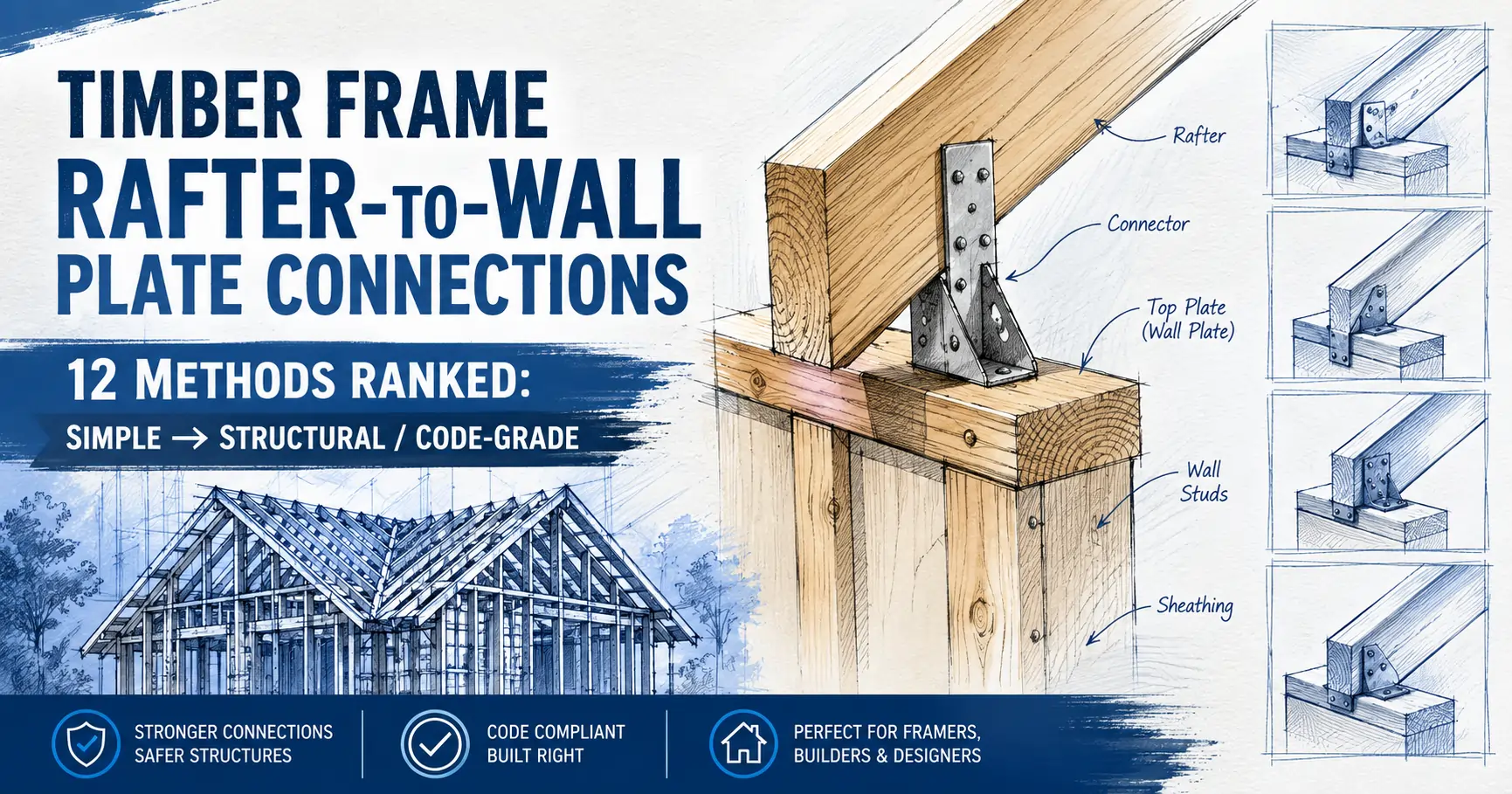
12 Methods Ranked: Simple → Structural / Code-Grade
If you’ve ever stared at a roof framing diagram and wondered how that sloped rafter actually stays attached to the wall below it, you’re not alone. This single joint — where the rafter foot meets the mauerlat (wall plate) — is one of the most important connections in an entire roof structure. Get it wrong, and you risk uplift failure in high wind. Get it right, and the roof transfers its load safely down into the wall.
Below are nine real methods used to make this connection, ranked roughly from simplest/DIY to fully engineered. Each one trades off cost, labor, and load capacity differently — so the “best” one depends entirely on what you’re building.
This ranking reflects the various characteristics of the rafter to wall connections from uplift resistance, load transfer reliability, and code acceptance and their application cases.
The selection of rafter to wall connection depends on the type of the timber frame, the available materials and manpower and the type of loads that act in the structure which in turn depends on the types of the application.
1. Toe-Nailing (Nails Only)
This most basic method that toe-nails the rafter directly into the wall plate. It’s fast and cheap, but it relies entirely on the nail’s shear strength and the wood’s grip on it.
Toe nailing does not resist uplift forces and its shear strength is low. This makes it best reserved for light-load structures like garden sheds or small outbuildings — not something you’d want holding up a roof in a storm-prone area.
Besides, It is suitable for non structural or semi structural connections like interior walls where there is no concern for heavy or uplift loads. It is usually used alongside other connections where they serve only to hold things in place during assembly and give extra strength.
Birdsmouth is sometimes avoided to prevent the reduction of rafter sizes due to creating notches since that can decrease the strength or the height for insulation required.
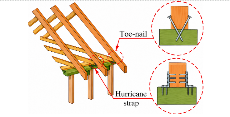
Toe nailing is applied by nailing at opposing angles through the rafter into the wall plate.
- Fastest, zero hardware
- Weak in uplift and withdrawal
- Highly dependent on wood quality and nail placement
Use: Temporary structures, sheds, very low wind zones
Failure mode: Nails pull out under uplift
2. Basic Steel Clip (Non-Rated)
A low-profile steel clip that grips both members without adding much bulk. Because it sits flatter than an angle bracket, it’s easy to hide under roofing membrane or trim. It handles minor lateral movement but isn’t engineered or rated for uplift resistance — more of a positioning aid than a structural wind connector.
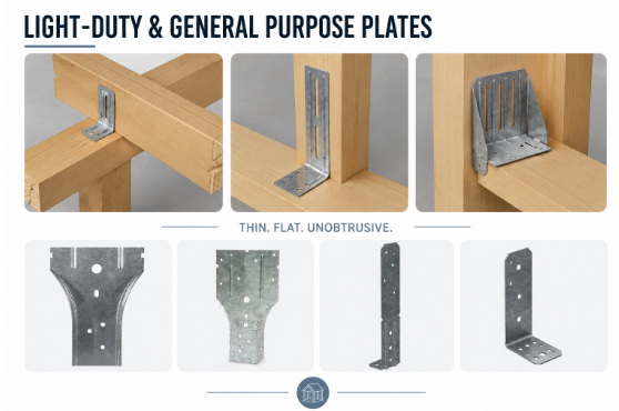
These connectors are made from thin plates and are not certified for any loads. They are used for non structural applications , as spacers or temporary layout purposes. They have long open slots that are used for adjusting the frames.
3. Skew Nailing + Bearing Seat (Basic Birdsmouth Only)
A small birdsmouth cut (seat + heel) plus toe-nailing.This Adds vertical bearing (important upgrade). However it is Still weak in uplift unless reinforced
Birdsmouth isn’t obsolete today — it’s still standard in traditional stick-frame roof construction.Its use is increasingly displaced by modern truss framing that places rafters just on plain timber plates without notches. However it is being avoided since it can reduce the strength of rafters.
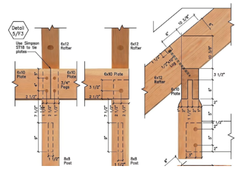
It is being avoided also for the need for higher heel height details for insulation purposes.metal connector systems that solve the same bearing problem without cutting into the wood are being increasingly used
Modern engineered lumber design of glulam and other rules forbid its application, and. There is restriction of creating notches in engineering wood like in I joists and lumber that limits its use.
Key rule: Seat cut depth ≤ 1/4 of rafter depth(IRC R802.7.1)
Use: Traditional carpentry, low-load roofs
4. Notch + Bearing Block (Load Distribution Upgrade)
Here, the rafter foot is notched to sit into a wooden support block (sometimes cut from rafter offcuts), increasing the bearing surface. This spreads the load over more wood fiber and reduces the risk of the rafter foot crushing or splitting under weight — a common failure point in simpler joints.
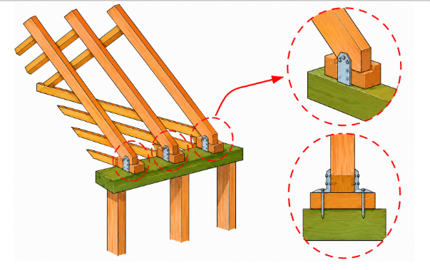
Adds a wood block under or beside the rafter seat.
- Increases bearing area
- Reduces crushing and splitting
- Often combined with metal connectors
Good practice: Especially for softer woods or higher loads
5. Simple Metal Angle (L-Bracket)
This is the connection you’ll see most often in framing designs of simple sheds,gazebos and other simple outdoor timber structures — a simple L-shaped steel bracket nailed or screwed into both the rafter and the wall plate.
It’s quick to install and offers a meaningful strength upgrade over nails alone, which is why it shows up in nearly every rafter-to-wallplate diagram, including the reference images this post is based on. Depending on the loads the structure is exposed to they can be engineered or not.
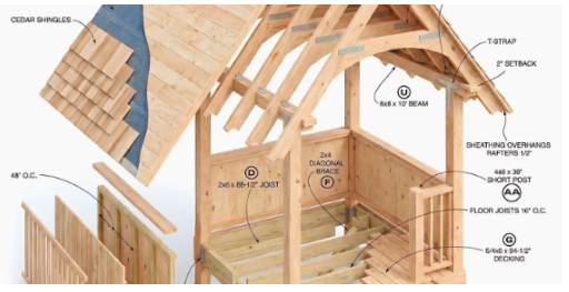
Metal L brackets can be engineered with certification of load rating on them or they can be also non-rated.
Light steel angle are fixed with nails or structural screws.
- Improves lateral and shear resistance
- Still moderate uplift capacity unless specifically rated
Common in: Light framing, DIY builds
6. Embedded Steel Connectors with engineered anchors (Cast-In situ Systems)
Steel anchors embedded into concrete bond beam or ring beam.
- Direct load path into structure
- Eliminates reliance on friction or nails
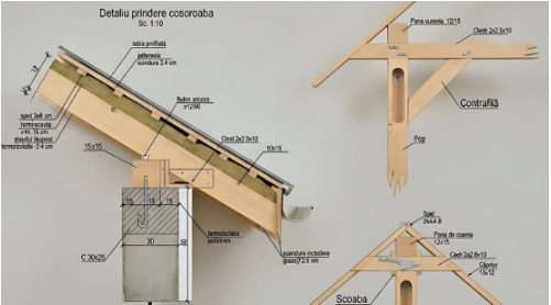
Typical embedment: ≥100 mm, but governed by anchor diameter, uplift/shear load, and concrete strength (per ACI 318 / Eurocode EN 1992-4 / AS 3600 or manufacturer ICC-ES/ETA data)
Use: High-load or engineered residential/commercial roofs
7. Engineered Bolted Steel Angle / Cleat
A step up from the basic bracket: a steel angle bolted through both the rafter and wall plate, rated for higher structural loads. The catch is precision — the notch cut into the rafter needs to stay shallow (generally under ¼ of the rafter’s height) or you risk weakening the timber right at its most stressed point.
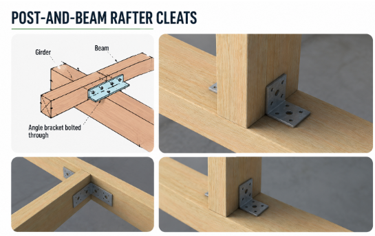
Heavy steel angle fixed with bolts (not nails).
- High shear and uplift capacity
- Requires drilling and precise alignment
Critical detail: Avoid over-notching rafter at connection
Use: Heavy timber, engineered builds
8. Engineered Rafter Clip / Light-Duty Hurricane Tie
A thin steel connector that wraps partially over or around one side of the rafter. Unlike a basic unrated clip, this style is specifically engineered for uplift resistance and performs meaningfully better than a generic bracket in wind loading. Manufacturer-specified nails must be used — substituting standard nails voids the rated uplift capacity. Common on standard residential roofs in moderate wind zones.
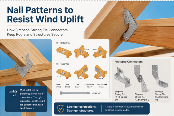
9. Engineered Strap Tie / Hurricane Tie (Wrap-Over Type)
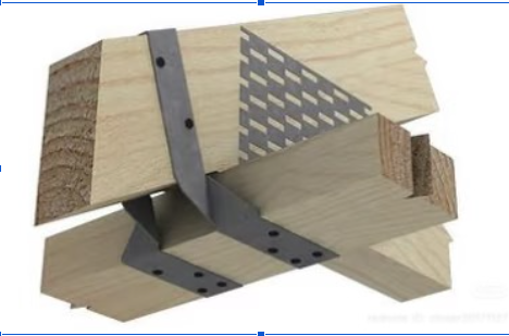
Instead of sitting to the side of the joint, this hardware wraps over or across the rafter and anchors directly into the wall plate. That top-down grip gives it noticeably stronger uplift resistance than side-mounted brackets, transferring wind load more directly into the wall system below. When this style is engineered and code-rated specifically for wind resistance, it’s typically called a hurricane tie — common examples include Simpson Strong-Tie’s H-series. This is the connection type you’ll see specified for code-compliant housing in wind-prone or hurricane-exposed regions.
.
Steel strap runs over the rafter and down the wall or plate.
- Excellent uplift resistance
- Ties roof into the wall system
Key advantage: Works even if geometry is imperfect
Use: seismic zones
10. Engineered Toothed Plate / Gang Nail Plate
A metal plate with small punched teeth pressed directly into both wood faces. It spreads the connection load across a wider area of fibers instead of concentrating it at a few nail points, which is part of why this style is common in prefabricated roof trusses.
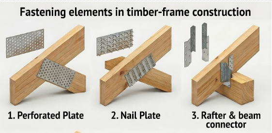
Pressed steel plate with integral teeth.
- Distributes load across many fibers
- Not intended for site hammering (requires press)
Common in: Prefabricated trusses
Note: Rare for site-built rafters unless engineered
11.Engineered Anchor Bolt to wall timber plate + Connector ties or Strap System
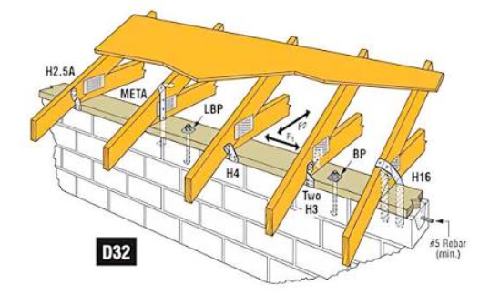
This is a rated engineering code compliant system that consists of anchors, connector ties and straps. The model numbers labeled on this drawing (such as H2.5A, H4, H3, H16, and META) are proprietary, highly engineered structural connectors manufactured by Simpson Strong-Tie.
This System ties everything together:
- Anchor bolts fix wall plate to concrete
- Strap or connector ties rafter to plate
This is key: The connection is only as strong as the weakest link
Use: Most code-compliant masonry construction
Why the Connections in this Diagram are Engineered
- Certified Model Numbers: The labels point directly to code-listed, rated hardware. For example, the H2.5A and H4 are code-approved hurricane ties designed to resist specific wind uplift forces.
- Defined Load Paths F1 and F2: Notice the black arrows labeled F1 and F2 in the center. Those represent the exact directional forces (lateral and longitudinal shear forces) that engineers calculate to ensure the roof doesn’t slide or blow off the wall.
- Engineered Anchorage: The diagram doesn’t just show the wood connectors; it shows a complete engineered system. It includes the BP (Bearing Plate), LBP (Long Bearing Plate), and anchor bolts embedded into concrete masonry blocks reinforced with a #5 Rebar (min.) to transfer the roof loads safely down into the foundation
12. Engineered anchor bolt rafter to concrete ring beam Connector Systems
These connectors are Pre-rated for resisting uplift and seismic forces. They are tested and certified with labels of their capacity engraved or written on their surface. Examples of manufactured connectors have codes like HGT-2, PA28, LGT2, LTA2, MGT, and VGT-. They can be paired with rebar embedded directly into the concrete or masonry wall. These systems are designed and load-rated for code compliance, with specific rebar embedment depths (commonly a 4″ minimum) required for the connection to perform as engineered. This is the method you’ll see specified when a project needs to pass structural inspection.
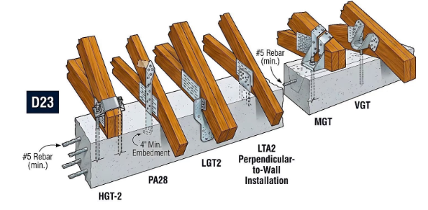
These connectors are verified for certain loading code compliance (Eurocode / ICC compliant).
- Designed for specific wind/snow loads
- Includes uplift, lateral, and seismic performance
Examples:
- Simpson Strong-Tie systems
- Custom fabricated steel connectors
Use: Required for permits, inspections, and high-risk zones
What Actually Matters Structurally (Often Missed)
A strong connector alone doesn’t guarantee a strong roof. The load path must be continuous:
Roof → Rafter → Connector → Wall Plate → Anchor → Wall → Foundation
If any link is weak, the system fails there first.
Critical Hidden Layers (Refined + Expanded)
These are not optional in serious construction:
- Wall plate (mauerlat): Distributes load along the wall
- Anchor bolts / threaded rods: Lock plate to structure
- Reinforced concrete bond beam (ring beam): Prevents wall spreading and cracking
- Waterproof membrane (DPC): Stops capillary moisture
- Birdsmouth cut: Provides stable bearing geometry
- Connector hardware: Handles uplift and lateral forces
- Optional insulation break: Reduces thermal bridging in modern builds
Common Mistakes (Important Additions)
- Over-cutting the birdsmouth → weakens rafter at highest stress point
- Using wrong nails in connectors → drastically reduces rated capacity
- Assuming weight alone prevents uplift → wind can exceed roof dead load
- Skipping the anchor system → entire roof can detach as a unit
- Mixing incompatible metals → corrosion over time
Practical Example
A small shed might use:
- Birdsmouth + toe nails
A typical house roof in France:
- Birdsmouth
- Hurricane tie
- Anchor-bolted wall plate on reinforced bond beam
A high-wind coastal structure:
- Engineered connectors
- Continuous steel straps
- Embedded anchors into reinforced concrete
DIY vs. Code-Compliant: Which Bucket Are You In?
Light duty / DIY-friendly: Nails, steel clips, angle brackets, notch + support block
Engineered / inspection-grade: Toothed nail plates, bolted steel angles, manufactured hardware systems with rebar embedment
If you’re building something load-bearing on a permitted structure, it’s worth having an engineer confirm which category your roof actually needs — wind and snow loads vary a lot by region, and the “right” connection for a shed in a calm climate isn’t the right one for a house roof in a high-wind zone.
Improved Classification (Clearer Than DIY vs Engineered)
Instead of two buckets, think in three:
- Basic carpentry: Nails, birdsmouth
- Reinforced carpentry: Brackets, ties, straps
- Structural systems: Bolted, embedded, engineered connectors